Tutorial for Linear Dimensions
The Dimension entity is the generic entity for all
dimension types, but unfortunately AutoCAD is not willing to show a
dimension line defined only by this dimension entity, it also needs an anonymous
block which contains the dimension line shape constructed by DXF primitives
like LINE and TEXT entities, this representation is called the dimension line
rendering in this documentation, beside the fact that this is not a real
graphical rendering. BricsCAD is a much more friendly CAD application, which
do show the dimension entity without the graphical rendering as block, which was
very useful for testing, because there is no documentation how to apply all the
dimension style variables (more than 80).
This seems to be the reason why dimension lines are rendered so differently by
many CAD application.
Don’t expect to get the same rendering results by ezdxf as you get from AutoCAD. Ezdxf tries to be as close to the results rendered by BricsCAD, but it is not possible to implement all the various combinations of dimension style parameters, which often affect one another.
Note
Ezdxf does not consider all DIMSTYLE variables, so the rendering results are different from CAD applications.
Text rendering is another problem, because ezdxf has no real rendering engine. Some font properties, like the real text width, which is only available to ezdxf if the Matplotlib package is installed and this value may also vary slightly for different CAD applications. Without access to the Matplotlib package the text properties in ezdxf are based on an abstract monospaced font and are bigger than required by true type fonts.
Not all DIMENSION and DIMSTYLE features are supported by all DXF versions, especially DXF R12 does not support many features, but in this case the required rendering of dimension lines is an advantage, because if the application just shows the rendered block, all features which can be used in DXF R12 will be displayed, but these features will disappear if the dimension line will be edited in the CAD application. Ezdxf writes only the supported DIMVARS of the used DXF version to avoid invalid DXF files. So it is not that critical to know all the supported features of a DXF version, except for limits and tolerances, ezdxf uses the advanced features of the MTEXT entity to create limits and tolerances and therefore they are not supported (displayed) in DXF R12 files.
See also
Graphical reference of many DIMVARS and some advanced information: DIMSTYLE Table
Source code file standards.py shows how to create your own DIMSTYLES.
The Script dimension_linear.py shows examples for linear dimensions.
Horizontal Dimension
import ezdxf

# Create a DXF R2010 document:
# Use argument setup=True to setup the default dimension styles.
doc = ezdxf.new("R2010", setup=True)

# Add new dimension entities to the modelspace:
msp = doc.modelspace()

# Add a LINE entity for visualization, not required to create the DIMENSION
# entity:
msp.add_line((0, 0), (3, 0))

# Add a horizontal linear DIMENSION entity:
dim = msp.add_linear_dim(
    base=(3, 2),  # location of the dimension line
    p1=(0, 0),  # 1st measurement point
    p2=(3, 0),  # 2nd measurement point
    dimstyle="EZDXF",  # default dimension style
)

# Necessary second step to create the BLOCK entity with the dimension geometry.
# Additional processing of the DIMENSION entity could happen between adding
# the entity and the rendering call.
dim.render()
doc.saveas("dim_linear_horiz.dxf")
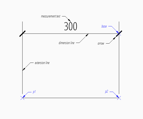
The example above creates a horizontal Dimension entity.
The default dimension style “EZDXF” is defined as:
1 drawing unit = 1m
measurement text height = 0.25 (drawing scale = 1:100)
the length factor
dimlfac= 100, which creates a measurement text in cm.arrow is “ARCHTICK”, arrow size
dimasz= 0.175
Every dimension style which does not exist will be replaced by the dimension
style “Standard” at DXF export by save() or saveas()
(e.g. dimension style setup was not initiated).
The base point defines the location of the dimension line, ezdxf accepts any point on the dimension line, the point p1 defines the start point of the first extension line, which also defines the first measurement point and the point p2 defines the start point of the second extension line, which also defines the second measurement point.
The return value dim is not a dimension entity, instead a
DimStyleOverride object is returned, the dimension
entity is stored as attribute dim.dimension.
Vertical and Rotated Dimension
Argument angle defines the angle of the dimension line in relation to the x-axis of the WCS or UCS, measurement is the distance between first and second measurement point in direction of angle.
# assignment to dim is not necessary, if no additional processing happens
msp.add_linear_dim(base=(3, 2), p1=(0, 0), p2=(3, 0), angle=-30).render()
doc.saveas("dim_linear_rotated.dxf")
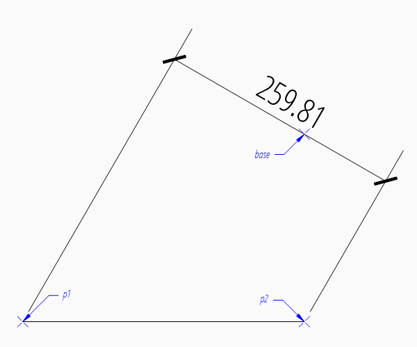
For a vertical dimension set argument angle to 90 degree, but in this example the vertical distance would be 0.
Aligned Dimension
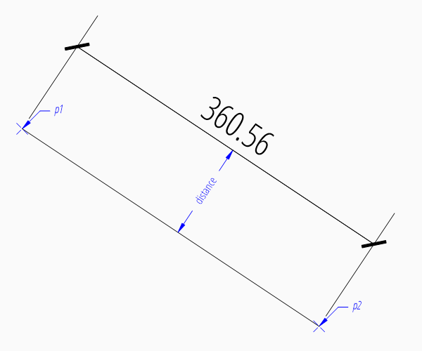
An aligned dimension line is parallel to the line defined by the definition points p1 and p2. The placement of the dimension line is defined by the argument distance, which is the distance between the definition line and the dimension line. The distance of the dimension line is orthogonal to the base line in counter clockwise orientation.
msp.add_line((0, 2), (3, 0))
dim = msp.add_aligned_dim(p1=(0, 2), p2=(3, 0), distance=1)
doc.saveas("dim_linear_aligned.dxf")
Dimension Style Override
Many dimension styling options are defined by the associated
DimStyle entity.
But often you wanna change just a few settings without creating a new dimension
style, therefore the DXF format has a protocol to store this changed settings
in the dimension entity itself.
This protocol is supported by ezdxf and every factory function which creates
dimension entities supports the override argument.
This override argument is a simple Python dictionary (e.g.
override = {"dimtad": 4}, place measurement text below dimension line).
The overriding protocol is managed by the DimStyleOverride
object, which is returned by the most dimension factory functions.
Placing Measurement Text
The default location of the measurement text depends on various
DimStyle parameters and is applied if no user defined
text location is defined.
Default Text Locations
“Horizontal direction” means in direction of the dimension line and “vertical direction” means perpendicular to the dimension line direction.
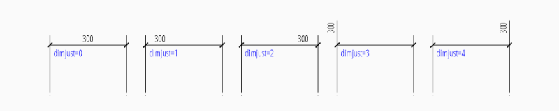
The “horizontal” location of the measurement text is defined by
dimjust:
0 |
Center of dimension line |
1 |
Left side of the dimension line, near first extension line |
2 |
Right side of the dimension line, near second extension line |
3 |
Over first extension line |
4 |
Over second extension line |
msp.add_linear_dim(
    base=(3, 2), p1=(0, 0), p2=(3, 0), override={"dimjust": 1}
).render()
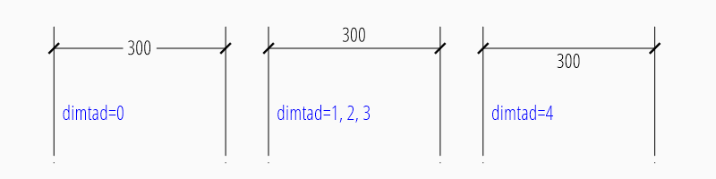
The “vertical” location of the measurement text relative to the dimension
line is defined by dimtad:
0 |
Center, it is possible to adjust the vertical location by
|
1 |
Above |
2 |
Outside, handled like Above by ezdxf |
3 |
JIS, handled like Above by ezdxf |
4 |
Below |
msp.add_linear_dim(
    base=(3, 2), p1=(0, 0), p2=(3, 0), override={"dimtad": 4}
).render()
The distance between text and dimension line is defined by
dimgap.
The DimStyleOverride object has a method
set_text_align() to set the default text
location in an easy way, this is also the reason for the 2 step creation process
of dimension entities:
dim = msp.add_linear_dim(base=(3, 2), p1=(0, 0), p2=(3, 0))
dim.set_text_align(halign="left", valign="center")
dim.render()
halign |
“left”, “right”, “center”, “above1”, “above2” |
valign |
“above”, “center”, “below” |
Run function example_for_all_text_placings_R2007() in the example script
dimension_linear.py to create a DXF file with all text placings supported by
ezdxf.
User Defined Text Locations
Beside the default location, it is possible to locate the measurement text freely.
Location Relative to Origin
The user defined text location can be set by the argument location in most dimension factory functions and always references the midpoint of the measurement text:
msp.add_linear_dim(
    base=(3, 2), p1=(3, 0), p2=(6, 0), location=(4, 4)
).render()
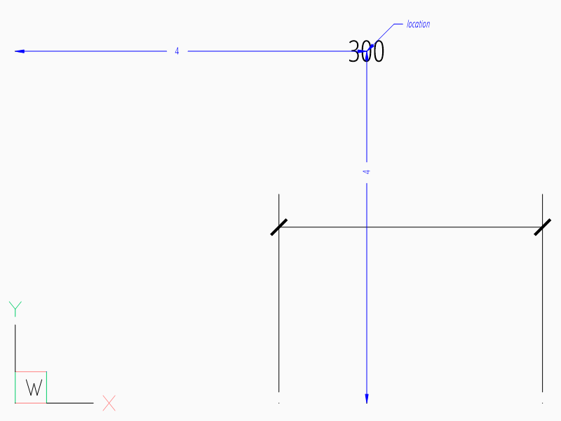
The location is relative to the origin of the active coordinate system or
WCS if no UCS is defined in the render()
method, the user defined location can also be set by
user_location_override().
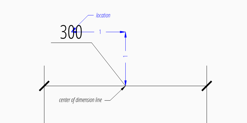
Location Relative to Center of Dimension Line
The method set_location() has additional
features for linear dimensions.
Argument leader = True adds a simple leader from the measurement text to
the center of the dimension line and argument relative = True places the
measurement text relative to the center of the dimension line.
dim = msp.add_linear_dim(base=(3, 2), p1=(3, 0), p2=(6, 0))
dim.set_location(location=(-1, 1), leader=True, relative=True)
dim.render()
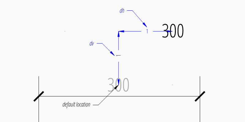
Location Relative to Default Location
The method shift_text() shifts the
measurement text away from the default text location. The shifting directions
are aligned to the text direction, which is the direction of the dimension line
in most cases, dh (for delta horizontal) shifts the text parallel to the text
direction, dv (for delta vertical) shifts the text perpendicular to the text
direction. This method does not support leaders.
dim = msp.add_linear_dim(base=(3, 2), p1=(3, 0), p2=(6, 0))
dim.shift_text(dh=1, dv=1)
dim.render()
Overriding Text Rotation
All factory methods supporting the argument text_rotation can override the measurement text rotation. The user defined rotation is relative to the render UCS x-axis (default is WCS).
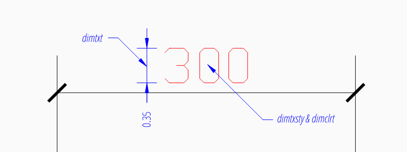
Measurement Text Formatting and Styling
Text Properties
DIMVAR |
Description |
|---|---|
|
Specifies the text style of the dimension as
|
|
Text height in drawing units. |
|
Measurement text color as AutoCAD Color Index (ACI). |
msp.add_linear_dim(
    base=(3, 2),
    p1=(3, 0),
    p2=(6, 0),
    override={
        "dimtxsty": "Standard",
        "dimtxt": 0.35,
        "dimclrt": 1,
    }
).render()
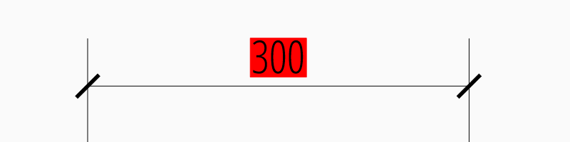
Background Filling
Background fillings are supported since DXF R2007, and ezdxf uses the MTEXT
entity to implement this feature, so setting background filling in DXF R12 has
no effect. The DIMVAR dimtfill defines the
kind of background filling and the DIMVAR dimtfillclr
defines the fill color.
DIMVAR |
Description |
|---|---|
|
Enables background filling if bigger than 0 |
|
Fill color as AutoCAD Color Index (ACI), if |
|
Description |
|---|---|
0 |
disabled |
1 |
canvas color |
2 |
color defined by |
msp.add_linear_dim(
    base=(3, 2),
    p1=(3, 0),
    p2=(6, 0),
    override={
        "dimtfill": 2,
        "dimtfillclr": 1,
    }
).render()
Text Formatting
decimal places:
dimdecdefines the number of decimal places displayed for the primary units of a dimension. (DXF R2000)decimal point character:
dimdsepdefines the decimal point as ASCII code, get the ASCII code byord('.')rounding:
dimrnd, rounds all dimensioning distances to the specified value, for instance, ifdimrndis set to 0.25, all distances round to the nearest 0.25 unit. Ifdimrndis set to 1.0, all distances round to the nearest integer. For more information look at the documentation of theezdxf.math.xround()function.zero trimming:
dimzin, ezdxf supports only a subset of values:4 to suppress leading zeros
8 to suppress trailing zeros
12 as the combination of both
measurement factor: scale measurement by factor
dimlfac, e.g. to get the dimensioning text in cm for a DXF file where 1 drawing unit represents 1m, setdimlfacto 100.text template:
dimpost, “<>” represents the measurement text, e.g. “~<>cm” produces “~300cm” for measurement in previous example.
To set this values the ezdxf.entities.DimStyle.set_text_format() and
ezdxf.entities.DimStyleOverride.set_text_format() methods are very
recommended.
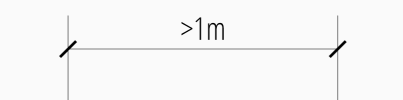
Overriding Measurement Text
This feature allows overriding the real measurement text by a custom
measurement text, the text is stored as string in the
Dimension entity as attribute
text.
Special values of the text attribute are: one space “ “ to suppress the
measurement text at all, an empty string “” or “<>” to display the real
measurement.
All factory functions have an explicit text argument, which always replaces the text value in the dxfattribs dict.
msp.add_linear_dim(base=(3, 2), p1=(3, 0), p2=(6, 0), text=">1m").render()
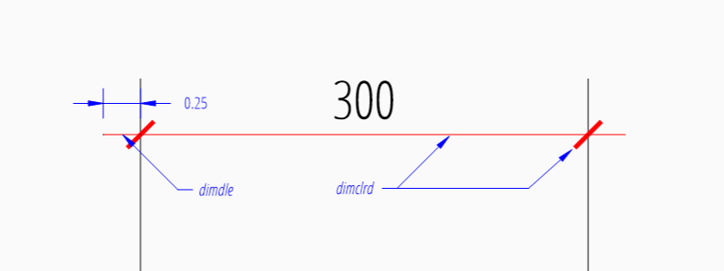
Dimension Line Properties
The dimension line color is defined by the DIMVAR dimclrd as AutoCAD Color Index (ACI),
dimclrd and also defines the color of the arrows. The linetype is
defined by dimltype and requires DXF R2007. The lineweight is defined
by dimlwd and requires DXF R2000, see also the
lineweight reference for valid values.
The dimdle is the extension of the dimension line beyond the extension
lines, this dimension line extension is not supported for all arrows.
DIMVAR |
Description |
|---|---|
|
dimension line and arrows color as AutoCAD Color Index (ACI) |
|
linetype of dimension line |
|
line weight of dimension line |
|
extension of dimension line in drawing units |
msp.add_linear_dim(
    base=(3, 2),
    p1=(3, 0),
    p2=(6, 0),
    override={
        "dimclrd": 1,  # red
        "dimdle": 0.25,
        "dimltype": "DASHED2",
        "dimlwd": 35,  # 0.35mm line weight
    }
).render()
DimStyleOverride() method:
dim = msp.add_linear_dim(base=(3, 2), p1=(3, 0), p2=(6, 0))
dim.set_dimline_format(
    color=1, linetype="DASHED2", lineweight=35, extension=0.25
)
dim.render()
Extension Line Properties
The extension line color is defined by the DIMVAR dimclre as AutoCAD Color Index (ACI).
The linetype for the first and the second extension line is defined by
dimltex1 and dimltex2 and requires DXF R2007.
The lineweight is defined by dimlwe and required DXF R2000, see also
the lineweight reference for valid
values.
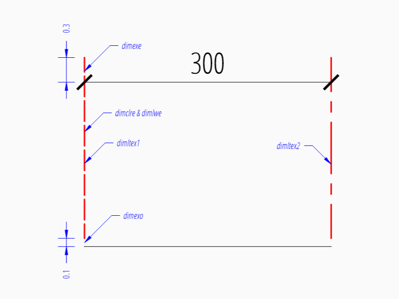
The dimexe is the extension of the extension line beyond the dimension
line, and dimexo defines the offset of the extension line from the
measurement point.
DIMVAR |
Description |
|---|---|
|
extension line color as AutoCAD Color Index (ACI) |
|
linetype of first extension line |
|
linetype of second extension line |
|
line weight of extension line |
|
extension beyond dimension line in drawing units |
|
offset of extension line from measurement point |
|
set to 1 to enable fixed length extension line |
|
length of fixed length extension line in drawing units |
|
suppress first extension line if 1 |
|
suppress second extension line if 1 |
msp.add_linear_dim(
    base=(3, 2),
    p1=(3, 0),
    p2=(6, 0),
    override={
        "dimclre": 1,   # red
        "dimltex1": "DASHED2",
        "dimltex2": "CENTER2",
        "dimlwe": 35,   # 0.35mm line weight
        "dimexe": 0.3,  # length above dimension line
        "dimexo": 0.1,  # offset from measurement point
    }
).render()
DimStyleOverride() methods:
dim = msp.add_linear_dim(base=(3, 2), p1=(3, 0), p2=(6, 0))
dim.set_extline_format(color=1, lineweight=35, extension=0.3, offset=0.1)
dim.set_extline1(linetype="DASHED2")
dim.set_extline2(linetype="CENTER2")
dim.render()
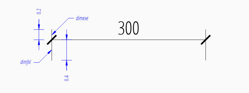
Fixed length extension lines are supported in DXF R2007, set dimfxlon
to 1 and dimfxl defines the length of the extension line starting at the
dimension line.
msp.add_linear_dim(
    base=(3, 2),
    p1=(3, 0),
    p2=(6, 0),
    override={
        "dimfxlon": 1,  # fixed length extension lines
        "dimexe": 0.2,  # length above dimension line
        "dimfxl": 0.4,  # length below dimension line
    }
).render()
DimStyleOverride() method:
dim = msp.add_linear_dim(base=(3, 2), p1=(3, 0), p2=(6, 0))
dim.set_extline_format(extension=0.2, fixed_length=0.4)
dim.render()
To suppress extension lines set dimse1 to 1 to suppress the first
extension line and dimse2 to 1 to suppress the second extension line.
msp.add_linear_dim(
    base=(3, 2),
    p1=(3, 0),
    p2=(6, 0),
    override={
        "dimse1": 1,  # suppress first extension line
        "dimse2": 1,  # suppress second extension line
        "dimblk": ezdxf.ARROWS.closed_filled,  # arrows just looks better
    }
).render()
DimStyleOverride() methods:
dim = msp.add_linear_dim(base=(3, 2), p1=(3, 0), p2=(6, 0))
dim.set_arrows(blk=ezdxf.ARROWS.closed_filled)
dim.set_extline1(disable=True)
dim.set_extline2(disable=True)
dim.render()
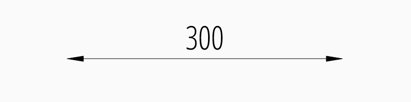
Arrows
“Arrows” mark then beginning and the end of a dimension line, and most of them do not look like arrows.
DXF distinguish between the simple tick (a slanted line) and arrows as blocks.
To use a simple tick as “arrow” set dimtsz
to a value greater than 0, this also disables arrow blocks as side effect:
dim = msp.add_linear_dim(base=(3, 2), p1=(3, 0), p2=(6, 0))
dim.set_tick(size=0.25)
dim.render()
Ezdxf uses the “ARCHTICK” block at double size to render the tick (AutoCAD and BricsCad just draw a simple line), so there is no advantage of using the tick instead of an arrow.
Using arrows:
dim = msp.add_linear_dim(base=(3, 2), p1=(3, 0), p2=(6, 0))
dim.set_arrow(blk="OPEN_30", size=0.25)
dim.render()
DIMVAR |
Description |
|---|---|
|
tick size in drawing units, set to 0 to use arrows |
|
set both arrow block names at once |
|
first arrow block name |
|
second arrow block name |
|
arrow size in drawing units |
msp.add_linear_dim(
    base=(3, 2),
    p1=(3, 0),
    p2=(6, 0),
    override={
        "dimtsz": 0,  # set tick size to 0 to enable arrow usage
        "dimasz": 0.25,  # arrow size in drawing units
        "dimblk": "OPEN_30",  # arrow block name
    }
).render()
The dimension line extension (dimdle) works only for a few arrow
blocks and the simple tick:
“ARCHTICK”
“OBLIQUE”
“NONE”
“SMALL”
“DOTSMALL”
“INTEGRAL”
Arrow Shapes
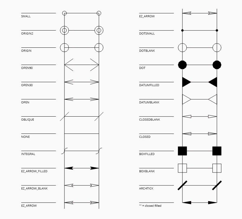
Arrow Names
The arrow names are stored as attributes in the ezdxf.ARROWS object.
closed_filled |
“” (empty string) |
dot |
“DOT” |
dot_small |
“DOTSMALL” |
dot_blank |
“DOTBLANK” |
origin_indicator |
“ORIGIN” |
origin_indicator_2 |
“ORIGIN2” |
open |
“OPEN” |
right_angle |
“OPEN90” |
open_30 |
“OPEN30” |
closed |
“CLOSED” |
dot_smallblank |
“SMALL” |
none |
“NONE” |
oblique |
“OBLIQUE” |
box_filled |
“BOXFILLED” |
box |
“BOXBLANK” |
closed_blank |
“CLOSEDBLANK” |
datum_triangle_filled |
“DATUMFILLED” |
datum_triangle |
“DATUMBLANK” |
integral |
“INTEGRAL” |
architectural_tick |
“ARCHTICK” |
ez_arrow |
“EZ_ARROW” |
ez_arrow_blank |
“EZ_ARROW_BLANK” |
ez_arrow_filled |
“EZ_ARROW_FILLED” |
Tolerances and Limits
The tolerances and limits features are implemented by using inline codes for
the MText entity, therefore DXF R2000 is required.
It is not possible to use both tolerances and limits at the same time.
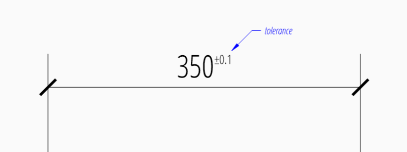
Tolerances
Geometrical tolerances are shown as additional text appended to the measurement
text. It is recommend to use set_tolerance()
method in DimStyleOverride or DimStyle.
The attribute dimtp defines the upper tolerance value, dimtm
defines the lower tolerance value if present, else the lower tolerance value is
the same as the upper tolerance value. Tolerance values are shown as given!
Same upper and lower tolerance value:
dim = msp.add_linear_dim(base=(0, 3), p1=(3, 0), p2=(6.5, 0))
dim.set_tolerance(.1, hfactor=.4, align="top", dec=2)
dim.render()
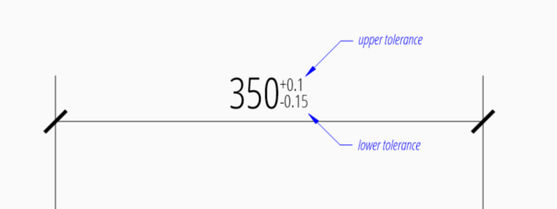
Different upper and lower tolerance values:
dim = msp.add_linear_dim(base=(0, 3), p1=(3, 0), p2=(6.5, 0))
dim.set_tolerance(upper=.1, lower=.15, hfactor=.4, align="middle", dec=2)
dim.render()
The attribute dimtfac specifies a scale factor for the text height of
limits and tolerance values relative to the dimension text height, as set by
dimtxt. For example, if dimtfac is set to 1.0, the text height
of fractions and tolerances is the same height as the dimension text.
If dimtxt is set to 0.75, the text height of limits and tolerances is
three-quarters the size of dimension text.
Vertical justification for tolerances is specified by dimtolj:
|
Description |
|---|---|
0 |
Align with bottom line of dimension text |
1 |
Align vertical centered to dimension text |
2 |
Align with top line of dimension text |
DIMVAR |
Description |
|---|---|
|
set to 1 to enable tolerances |
|
set the maximum (or upper) tolerance limit for dimension text |
|
set the minimum (or lower) tolerance limit for dimension text |
|
specifies a scale factor for the text height of limits and tolerance values
relative to the dimension text height, as set by |
|
4 to suppress leading zeros, 8 to suppress trailing zeros or 12 to
suppress both, like |
|
set the vertical justification for tolerance values relative to the nominal dimension text. |
|
set the number of decimal places to display in tolerance values |
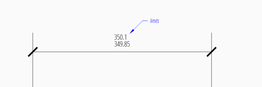
Limits
The geometrical limits are shown as upper and lower measurement limit and
replaces the usual measurement text. It is recommend to use
set_limits() method in
DimStyleOverride or DimStyle.
For limits the tolerance values are drawing units scaled by measurement factor
dimlfac, the upper limit is scaled measurement value + dimtp and
the lower limit is scaled measurement value - dimtm.
The attributes dimtfac, dimtzin and dimtdec have the
same meaning for limits as for tolerances.
dim = msp.add_linear_dim(base=(0, 3), p1=(3, 0), p2=(6.5, 0))
dim.set_limits(upper=.1, lower=.15, hfactor=.4, dec=2)
dim.render()
DIMVAR |
Description |
|---|---|
|
set to 1 to enable limits |
Alternative Units
Alternative units are not supported.