Tutorial for OCS/UCS Usage
For OCS/UCS usage is a basic understanding of vector math required, for a brush up, watch the YouTube tutorials of 3Blue1Brown about Linear Algebra.
Second read the Coordinate Systems introduction please.
See also
The free online book 3D Math Primer for Graphics and Game Development is a very good resource for learning vector math and other graphic related topics, it is easy to read for beginners and especially targeted to programmers.
For WCS there is not much to say as, it is what it is: the main world coordinate system, and a drawing unit can have any real world unit you want. Autodesk added some mechanism to define a scale for dimension and text entities, but because I am not an AutoCAD user, I am not familiar with it, and further more I think this is more an AutoCAD topic than a DXF topic.
Object Coordinate System (OCS)
The OCS is used to place planar 2D entities in 3D space. ALL points of a planar entity lay in the same plane, this is also true if the plane is located in 3D space by an OCS. There are three basic DXF attributes that gives a 2D entity its spatial form.
Extrusion
The extrusion vector defines the OCS, it is a normal vector to the base plane of
a planar entity. This base plane is always located in the origin of the
WCS. But there are some entities like Ellipse,
which have an extrusion vector, but do not establish an OCS. For this entities
the extrusion vector defines only the extrusion direction and thickness defines
the extrusion distance, but all other points and directions in WCS.
Elevation
The elevation value defines the z-axis value for all points of a planar entity, this is an OCS value, and defines the distance of the entity plane from the base plane.
This value exists only in output from DXF versions prior to R11 as separated DXF
attribute (group code 38). In DXF R12 and later, the elevation value is
supplied as z-axis value of each point. But as always in DXF, this simple rule
does not apply to all entities: LWPolyline and
Hatch have an DXF attribute elevation as a
3D point, where the z-values of this point is the elevation height and the
x-value and the y-value are 0.
Thickness
Defines the extrusion distance for an entity.
Note
There is a new edition of this tutorial using UCS based transformation, which are available in ezdxf v0.11 and later: Tutorial for UCS Based Transformations
This edition shows the hard way to accomplish the transformations by low level operations.
Placing 2D Circle in 3D Space
The colors of the system axis follow the AutoCAD standard:
red is x-axis
green is y-axis
blue is z-axis
import ezdxf
from ezdxf.math import OCS

doc = ezdxf.new('R2010')
msp = doc.modelspace()

# For this example the OCS is rotated around x-axis about 45 degree
# OCS z-axis: x=0, y=1, z=1
# extrusion vector must not normalized here
ocs = OCS((0, 1, 1))
msp.add_circle(
    # You can place the 2D circle in 3D space
    # but you have to convert WCS into OCS
    center=ocs.from_wcs((0, 2, 2)),
    # center in OCS: (0.0, 0.0, 2.82842712474619)
    radius=1,
    dxfattribs={
        # here the extrusion vector should be normalized,
        # which is granted by using the ocs.uz
        'extrusion': ocs.uz,
        'color': 1,
    })
# mark center point of circle in WCS
msp.add_point((0, 2, 2), dxfattribs={'color': 1})
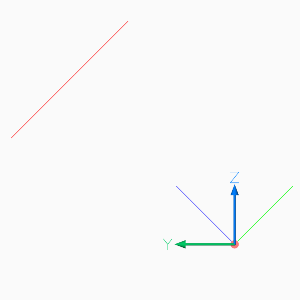
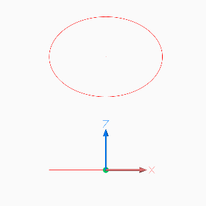
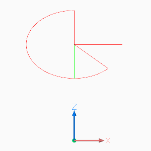
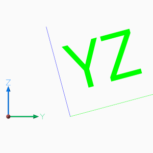
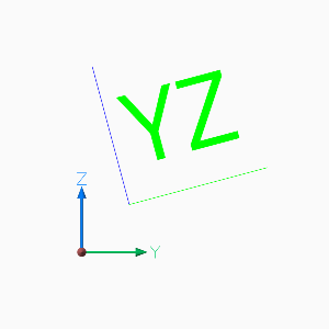
The following image shows the 2D circle in 3D space in AutoCAD Left and Front view. The blue line shows the OCS z-axis (extrusion direction), elevation is the distance from the origin to the center of the circle in this case 2.828, and you see that the x- and y-axis of the OCS and the WCS are not aligned.
Placing LWPolyline in 3D Space
For simplicity of calculation I use the UCS class in this example to
place a 2D pentagon in 3D space.
# The center of the pentagon should be (0, 2, 2), and the shape is
# rotated around x-axis about 45 degree, to accomplish this I use an
# UCS with z-axis (0, 1, 1) and an x-axis parallel to WCS x-axis.
ucs = UCS(
    origin=(0, 2, 2),  # center of pentagon
    ux=(1, 0, 0),  # x-axis parallel to WCS x-axis
    uz=(0, 1, 1),  # z-axis
)
# calculating corner points in local (UCS) coordinates
points = [Vec3.from_deg_angle((360 / 5) * n) for n in range(5)]
# converting UCS into OCS coordinates
ocs_points = list(ucs.points_to_ocs(points))

# LWPOLYLINE accepts only 2D points and has an separated DXF attribute elevation.
# All points have the same z-axis (elevation) in OCS!
elevation = ocs_points[0].z

msp.add_lwpolyline(
    points=ocs_points,
    format='xy',  # ignore z-axis
    close=True,
    dxfattribs={
        'elevation': elevation,
        'extrusion': ucs.uz,
        'color': 1,
    })
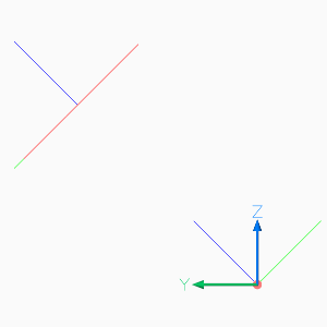
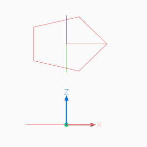
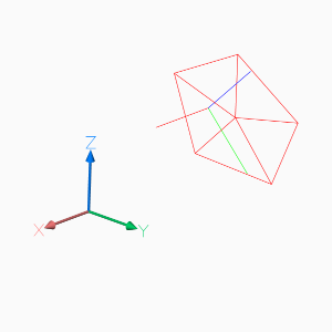
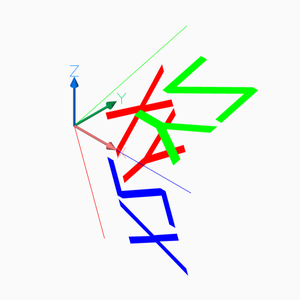
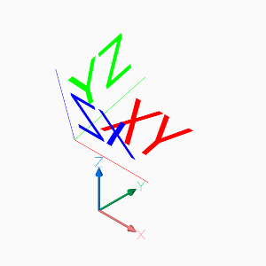
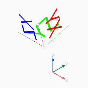
The following image shows the 2D pentagon in 3D space in AutoCAD Left, Front and Top view. The three lines from the center of the pentagon show the UCS, the three colored lines in the origin show the OCS, the white lines in the origin show the WCS.
The z-axis of the UCS and the OCS pointing in the same direction (extrusion direction), and the x-axis of the UCS and the WCS pointing also in the same direction. The elevation is the distance from the origin to the center of the pentagon and all points of the pentagon have the same elevation, and you see that the y-axis of the UCS, the OCS and the WCS are not aligned.
Using UCS to Place 3D Polyline
It is much simpler to use a 3D Polyline to create the
3D pentagon. The UCS class is handy for this example and all kind of
3D operations.
# Using an UCS simplifies 3D operations, but UCS definition can happen later
# calculating corner points in local (UCS) coordinates without Vec3 class
angle = math.radians(360 / 5)
corners_ucs = [(math.cos(angle * n), math.sin(angle * n), 0) for n in range(5)]

# let's do some transformations
tmatrix = Matrix44.chain(  # creating a transformation matrix
    Matrix44.z_rotate(math.radians(15)),  # 1. rotation around z-axis
    Matrix44.translate(0, .333, .333),  # 2. translation
)
transformed_corners_ucs = tmatrix.transform_vertices(corners_ucs)

# transform UCS into WCS
ucs = UCS(
    origin=(0, 2, 2),  # center of pentagon
    ux=(1, 0, 0),  # x-axis parallel to WCS x-axis
    uz=(0, 1, 1),  # z-axis
)
corners_wcs = list(ucs.points_to_wcs(transformed_corners_ucs))

msp.add_polyline3d(
    points=corners_wcs,
    close=True,
)

# add lines from center to corners
center_wcs = ucs.to_wcs((0, .333, .333))
for corner in corners_wcs:
    msp.add_line(center_wcs, corner, dxfattribs={'color': 1})

ucs.render_axis(msp)
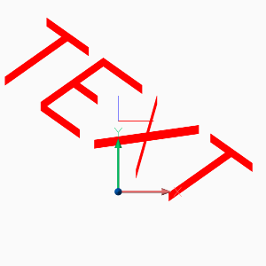
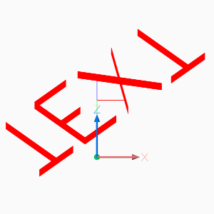
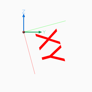
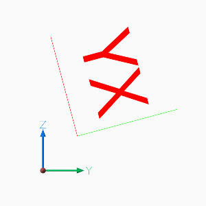
Placing 2D Text in 3D Space
The problem of placing text in 3D space is the text rotation, which is always
counter clockwise around the OCS z-axis, and 0 degree is the direction of
the positive OCS x-axis, and the OCS x-axis is calculated by the
Arbitrary Axis Algorithm.
Calculate the OCS rotation angle by converting the TEXT rotation angle (in UCS
or WCS) into a vector or begin with text direction as vector, transform this
direction vector into OCS and convert the OCS vector back into an angle in the
OCS xy-plane (see example), this procedure is available as
UCS.to_ocs_angle_deg() or UCS.to_ocs_angle_rad().
AutoCAD supports thickness for the TEXT entity only for .shx fonts and not for true type fonts.
# Thickness for text works only with shx fonts not with true type fonts
doc.styles.new('TXT', dxfattribs={'font': 'romans.shx'})

ucs = UCS(origin=(0, 2, 2), ux=(1, 0, 0), uz=(0, 1, 1))
# calculation of text direction as angle in OCS:
# convert text rotation in degree into a vector in UCS
text_direction = Vec3.from_deg_angle(-45)
# transform vector into OCS and get angle of vector in xy-plane
rotation = ucs.to_ocs(text_direction).angle_deg

text = msp.add_text(
    text="TEXT",
    dxfattribs={
        # text rotation angle in degrees in OCS
        'rotation': rotation,
        'extrusion': ucs.uz,
        'thickness': .333,
        'color': 1,
        'style': 'TXT',
    })
# set text position in OCS
text.set_pos(ucs.to_ocs((0, 0, 0)), align='MIDDLE_CENTER')
Hint
For calculating OCS angles from an UCS, be aware that 2D entities, like TEXT or ARC, are placed parallel to the xy-plane of the UCS.
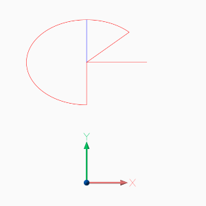
Placing 2D Arc in 3D Space
Here we have the same problem as for placing text, you need the start- and end angle of the arc in degrees in the OCS, and this example also shows a shortcut for calculating the OCS angles.
ucs = UCS(origin=(0, 2, 2), ux=(1, 0, 0), uz=(0, 1, 1))
msp.add_arc(
    center=ucs.to_ocs((0, 0)),
    radius=1,
    start_angle=ucs.to_ocs_angle_deg(45),
    end_angle=ucs.to_ocs_angle_deg(270),
    dxfattribs={
        'extrusion': ucs.uz,
        'color': 1,
    })
center = ucs.to_wcs((0, 0))
msp.add_line(
    start=center,
    end=ucs.to_wcs(Vec3.from_deg_angle(45)),
    dxfattribs={'color': 1},
)
msp.add_line(
    start=center,
    end=ucs.to_wcs(Vec3.from_deg_angle(270)),
    dxfattribs={'color': 1},
)
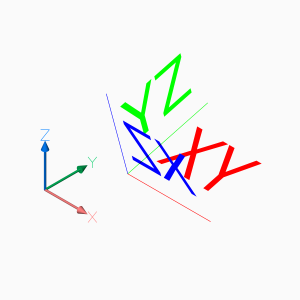
Placing Block References in 3D Space
Despite the fact that block references (Insert) can
contain true 3D entities like Line or
Mesh, the Insert entity uses
the same placing principe as Text or
Arc shown in the previous chapters.
Placement by OCS coordinates and rotation about the OCS z-axis, can be achieved
the same way as for generic 2D entities. The DXF attribute
Insert.dxf.rotation rotates a block reference around the block z-axis,
which is located in the Block.dxf.base_point. To rotate the block reference
around the WCS x-axis, a transformation of the block z-axis into the WCS x-axis
is required by rotating the block z-axis 90 degree counter-clockwise around
y-axis by using an UCS:
This is just an excerpt of the important parts, see the whole code of insert.py at github.
# rotate UCS around an arbitrary axis:
def ucs_rotation(ucs: UCS, axis: Vec3, angle: float):
    # new in ezdxf v0.11: UCS.rotate(axis, angle)
    t = Matrix44.axis_rotate(axis, math.radians(angle))
    ux, uy, uz = t.transform_vertices([ucs.ux, ucs.uy, ucs.uz])
    return UCS(origin=ucs.origin, ux=ux, uy=uy, uz=uz)


doc = ezdxf.new('R2010', setup=True)
blk = doc.blocks.new('CSYS')
setup_csys(blk)
msp = doc.modelspace()

ucs = ucs_rotation(UCS(), axis=Y_AXIS, angle=90)
# transform insert location to OCS
insert = ucs.to_ocs((0, 0, 0))
# rotation angle about the z-axis (= WCS x-axis)
rotation = ucs.to_ocs_angle_deg(15)
msp.add_blockref('CSYS', insert, dxfattribs={
   'extrusion': ucs.uz,
   'rotation': rotation,
})
To rotate a block reference around another axis than the block z-axis, you have to find the rotated z-axis (extrusion vector) of the rotated block reference, following example rotates the block reference around the block x-axis by 15 degrees:
# t is a transformation matrix to rotate 15 degree around the x-axis
t = Matrix44.axis_rotate(axis=X_AXIS, angle=math.radians(15))
# transform block z-axis into new UCS z-axis (= extrusion vector)
uz = Vec3(t.transform(Z_AXIS))
# create new UCS at the insertion point, because we are rotating around the x-axis,
# ux is the same as the WCS x-axis and uz is the rotated z-axis.
ucs = UCS(origin=(1, 2, 0), ux=X_AXIS, uz=uz)
# transform insert location to OCS, block base_point=(0, 0, 0)
insert = ucs.to_ocs((0, 0, 0))
# for this case a rotation around the z-axis is not required
rotation = 0
blockref = msp.add_blockref('CSYS', insert, dxfattribs={
    'extrusion': ucs.uz,
    'rotation': rotation,
})
The next example shows how to translate a block references with an already established OCS:
# translate a block references with an established OCS
translation = Vec3(-3, -1, 1)
# get established OCS
ocs = blockref.ocs()
# get insert location in WCS
actual_wcs_location = ocs.to_wcs(blockref.dxf.insert)
# translate location
new_wcs_location = actual_wcs_location + translation
# convert WCS location to OCS location
blockref.dxf.insert = ocs.from_wcs(new_wcs_location)
Setting a new insert location is the same procedure without adding a translation vector, just transform the new insert location into the OCS.
The next operation is to rotate a block reference with an established OCS, rotation axis is the block y-axis, rotation angle is -90 degrees. First transform block y-axis (rotation axis) and block z-axis (extrusion vector) from OCS into WCS:
# rotate a block references with an established OCS around the block y-axis about 90 degree
ocs = blockref.ocs()
# convert block y-axis (= rotation axis) into WCS vector
rotation_axis = ocs.to_wcs((0, 1, 0))
# convert local z-axis (=extrusion vector) into WCS vector
local_z_axis = ocs.to_wcs((0, 0, 1))
Build transformation matrix and transform extrusion vector and build new UCS:
# build transformation matrix
t = Matrix44.axis_rotate(axis=rotation_axis, angle=math.radians(-90))
uz = t.transform(local_z_axis)
uy = rotation_axis
# the block reference origin stays at the same location, no rotation needed
wcs_insert = ocs.to_wcs(blockref.dxf.insert)
# build new UCS to convert WCS locations and angles into OCS
ucs = UCS(origin=wcs_insert, uy=uy, uz=uz)
Set new OCS attributes, we also have to set the rotation attribute even though we do not rotate the block reference around the local z-axis, the new block x-axis (0 deg) differs from OCS x-axis and has to be adjusted:
# set new OCS
blockref.dxf.extrusion = ucs.uz
# set new insert
blockref.dxf.insert = ucs.to_ocs((0, 0, 0))
# set new rotation: we do not rotate the block reference around the local z-axis,
# but the new block x-axis (0 deg) differs from OCS x-axis and has to be adjusted
blockref.dxf.rotation = ucs.to_ocs_angle_deg(0)
And here is the point, where my math knowledge ends, for more advanced CAD operation you have to look elsewhere.