Tutorial for Angular Dimensions
Please read the Tutorial for Linear Dimensions before, if you haven’t.
Note
Ezdxf does not consider all DIMSTYLE variables, so the rendering results are different from CAD applications.
Dimension Style “EZ_CURVED”
All factory methods to create angular dimensions uses the dimension style “EZ_CURVED” for curved dimension lines which is defined as:
angle unit is decimal degrees,
dimaunit= 0measurement text height = 0.25 (drawing scale = 1:100)
measurement text location is above the dimension line
closed filled arrow and arrow size
dimasz= 0.25dimazin= 2, suppresses trailing zeros (e.g. 12.5000 becomes 12.5)
This DIMENSION style only exist if the argument setup is True for creating
a new DXF document by ezdxf.new().
Every dimension style which does not exist will be replaced by the dimension
style “Standard” at DXF export by save() or saveas()
(e.g. dimension style setup was not initiated).
Add all ezdxf specific resources (line types, text- and dimension styles) to an existing DXF document:
import ezdxf
from ezdxf.tools.standards import setup_drawing

doc = ezdxf.readfile("your.dxf")
setup_drawing(doc, topics="all")
Factory Methods to Create Angular Dimensions
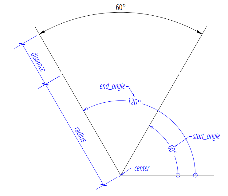
Defined by Center, Radius and Angles
The first example shows an angular dimension defined by the center point, radius, start- and end angles:
import ezdxf

# Create a DXF R2010 document:
# Use argument setup=True to setup the default dimension styles.
doc = ezdxf.new("R2010", setup=True)

# Add new entities to the modelspace:
msp = doc.modelspace()

# Add an angular DIMENSION defined by the center point, start- and end angles,
# the measurement text is placed at the default location above the dimension
# line:
dim = msp.add_angular_dim_cra(
    center=(5, 5),  # center point of the angle
    radius= 7,  # distance from center point to the start of the extension lines
    start_angle=60,  # start angle in degrees
    end_angle=120,  # end angle in degrees
    distance=3,  # distance from start of the extension lines to the dimension line
    dimstyle="EZ_CURVED",  # default angular dimension style
)

# Necessary second step to create the BLOCK entity with the dimension geometry.
# Additional processing of the DIMENSION entity could happen between adding
# the entity and the rendering call.
dim.render()
doc.saveas("angular_dimension_cra.dxf")
The return value dim is not a dimension entity, instead a
DimStyleOverride object is
returned, the dimension entity is stored as dim.dimension.
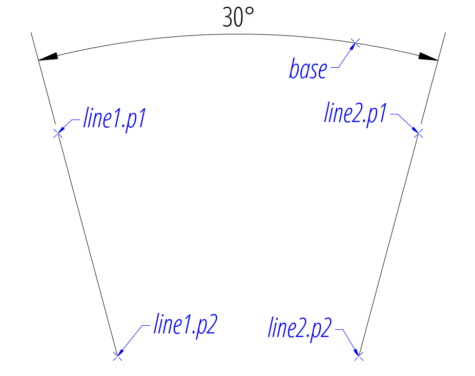
Angle by 2 Lines
The next example shows an angular dimension for an angle defined by two lines:
import ezdxf

doc = ezdxf.new(setup=True)
msp = doc.modelspace()

# Setup the geometric parameters for the DIMENSION entity:
base = (5.8833, -6.3408)  # location of the dimension line
p1 = (2.0101, -7.5156)  # start point of 1st leg
p2 = (2.7865, -10.4133)  # end point of 1st leg
p3 = (6.7054, -7.5156)  # start point of 2nd leg
p4 = (5.9289, -10.4133)  # end point of 2nd leg

# Draw the lines for visualization, not required to create the
# DIMENSION entity:
msp.add_line(p1, p2)
msp.add_line(p3, p4)

# Add an angular DIMENSION defined by two lines, the measurement text is
# placed at the default location above the dimension line:
dim = msp.add_angular_dim_2l(
    base=base,  # defines the location of the dimension line
    line1=(p1, p2),  # start leg of the angle
    line2=(p3, p4),  # end leg of the angle
    dimstyle="EZ_CURVED",  # default angular dimension style
)

# Necessary second step to create the dimension line geometry:
dim.render()
doc.saveas("angular_dimension_2l.dxf")
The example above creates an angular Dimension entity
to measures the angle between two lines (line1 and line2).
The base point defines the location of the dimension line (arc), any point on the dimension line is valid. The points p1 and p2 define the first leg of the angle, p1 also defines the start point of the first extension line. The points p3 and p4 define the second leg of the angle and point p3 also defines the start point of the second extension line.
The measurement of the DIMENSION entity is the angle enclosed by the first and the second leg and where the dimension line passes the base point.
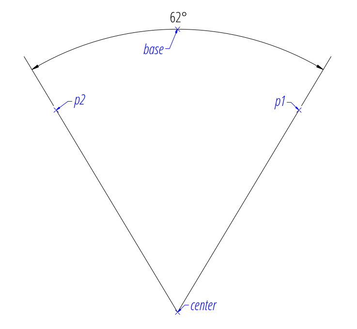
Angle by 3 Points
The next example shows an angular dimension defined by three points, a center point and the two end points of the angle legs:
import ezdxf

doc = ezdxf.new(setup=True)
msp = doc.modelspace()

msp.add_angular_dim_3p(
    base=(0, 7),  # location of the dimension line
    center=(0, 0),  # center point
    p1=(-3, 5),  # end point of 1st leg = start angle
    p2=(3, 5),  # end point of 2nd leg = end angle
).render()
Angle from ConstructionArc
The ezdxf.math.ConstructionArc provides various class methods for
creating arcs and the construction tool can be created from an ARC entity.
Add an angular dimension to an ARC entity:
import ezdxf

doc = ezdxf.new(setup=True)
msp = doc.modelspace()

arc = msp.add_arc(
    center=(0, 0),
    radius=5,
    start_angle = 60,
    end_angle = 120,
)
msp.add_angular_dim_arc(
    arc.construction_tool(),
    distance=2,
).render()
Placing Measurement Text
The default location of the measurement text depends on various
DimStyle parameters and is applied if no user defined
text location is defined.
Note
Not all possibles features of DIMSTYLE are supported by the ezdxf rendering procedure and especially for the angular dimension there are less features implemented than for the linear dimension because of the lack of good documentation.
See also
Graphical reference of many DIMVARS and some advanced information: DIMSTYLE Table
Source code file standards.py shows how to create your own DIMSTYLES.
The Script dimension_angular.py shows examples for angular dimensions.
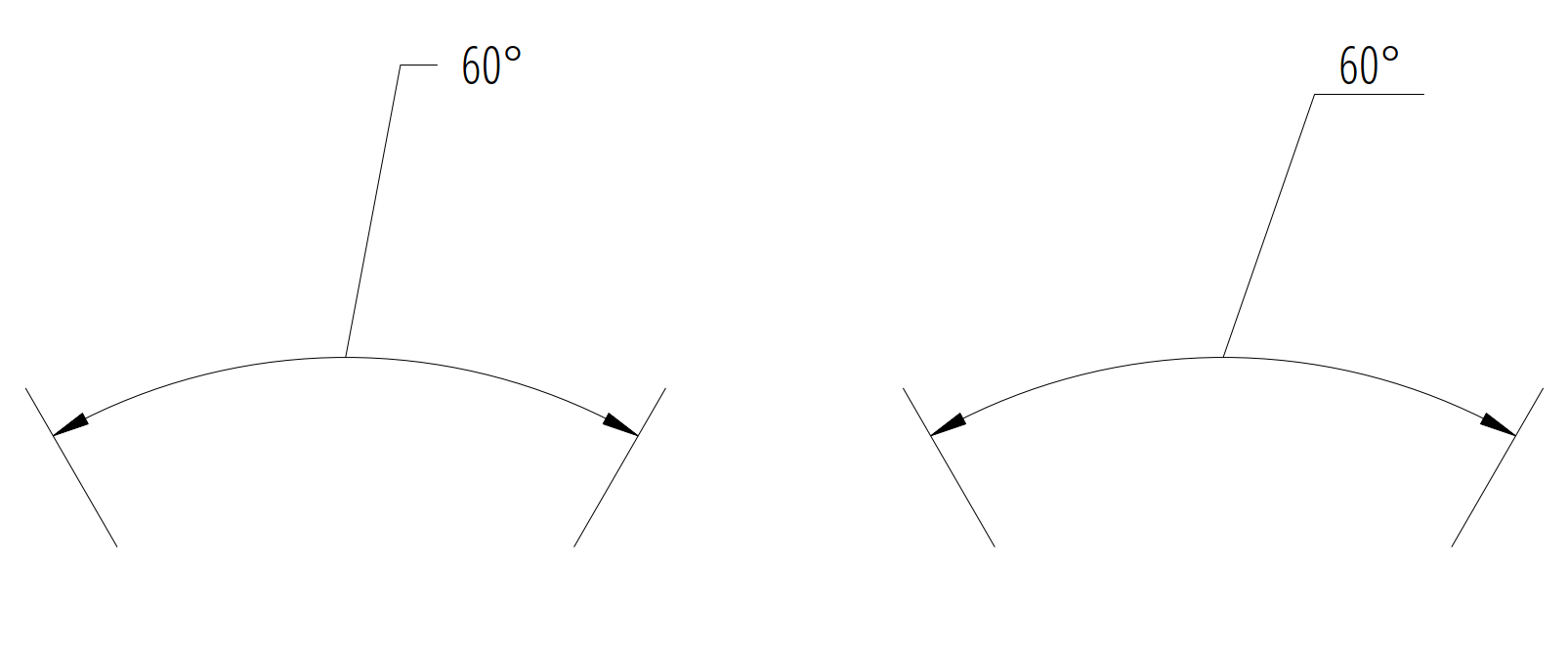
Default Text Locations
The DIMSTYLE “EZ_CURVED” places the measurement text in the center of the angle above the dimension line. The first examples above show the measurement text at the default text location.
The text direction angle is always perpendicular to the line from the text center to the center point of the angle unless this angle is manually overridden.
The “vertical” location of the measurement text relative to the dimension
line is defined by dimtad:
0 |
Center, it is possible to adjust the vertical location by
|
1 |
Above |
2 |
Outside, handled like Above by ezdxf |
3 |
JIS, handled like Above by ezdxf |
4 |
Below |
msp.add_angular_dim_cra(
    center=(3, 3),
    radius=3,
    distance=1,
    start_angle=60,
    end_angle=120,
    override={
        "dimtad": 1,  # 0=center; 1=above; 4=below;
    },
).render()
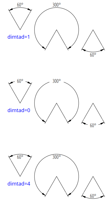
Arrows and measurement text are placed “outside” automatically if the available
space between the extension lines isn’t sufficient.
This overrides the dimtad value by 1 (“above”).
Ezdxf follows its own rules, ignores the dimatfit
attribute and works similar to dimatfit = 1, move arrows first, then text:
Shift Text From Default Location
The method shift_text() shifts the measurement text away from the default
location. The shifting direction is aligned to the text rotation of the default
measurement text.
dim = msp.add_angular_dim_cra(
    center=(3, 3),
    radius=3,
    distance=1,
    start_angle=60,
    end_angle=120,
)
# shift text from default text location:
dim.shift_text(0.5, 1.0)
dim.render()
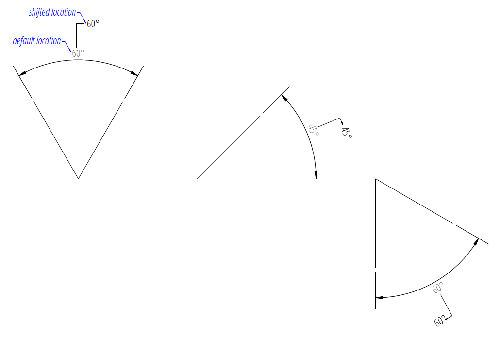
This is just a rendering effect, editing the dimension line in a CAD application resets the text to the default location.
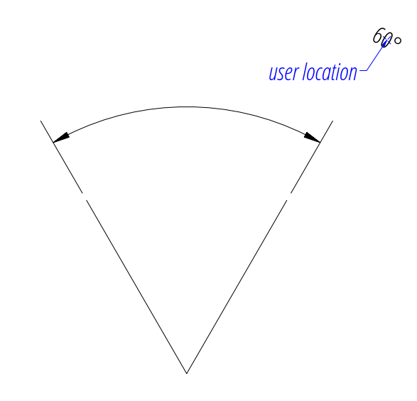
User Defined Text Locations
Beside the default location it is always possible to override the text location by a user defined location.
The coordinates of user locations are located in the rendering UCS and the default rendering UCS is the WCS.
Absolute User Location
Absolute placing of the measurement text means relative to the origin of the render UCS. The user location is stored in the DIMENSION entity, which means editing the dimension line in a CAD application does not alter the text location. This location also determines the rotation of the measurement text.
dim = msp.add_angular_dim_cra(
    center=(3, 3),
    radius=3,
    distance=1,
    start_angle=60,
    end_angle=120,
    location=(5, 8),  # user defined measurement text location
)
dim.render()
Relative User Location
Relative placing of the measurement text means relative to the middle of the
dimension line. This is only possible by calling the set_location()
method, and the argument relative has to be True.
The user location is stored in the DIMENSION entity, which means editing the
dimension line in a CAD application does not alter the text location.
This location also determines the rotation of the measurement text.
dim = msp.add_angular_dim_cra(
    center=(3, 3),
    radius=3,
    distance=1,
    start_angle=60,
    end_angle=120,
)
dim.set_location((1, 2), relative=True)
dim.render()
Adding a Leader
The method set_location() has the option to add a leader line to the
measurement text. This also aligns the text rotation to the render
UCS x-axis, this means in the default case the measurement text is horizontal.
The leader line can be “below” the text or start at the “left” or “right”
center of the text, this location is defined by the
dimtad attribute, 0 means “center” and
any value != 0 means “below”.
for dimtad, x in [(0, 0), (4, 6)]:
    dim = msp.add_angular_dim_cra(
        center=(3 + x, 3),
        radius=3,
        distance=1,
        start_angle=60,
        end_angle=120,
        override={"dimtad": dimtad}  # "center" == 0; "below" != 0;
    )
    dim.set_location((1, 2), relative=True, leader=True)
    dim.render()
Advanced version which calculates the relative text location: The user location vector has a length 2 and the orientation is defined by center_angle pointing away from the center of the angle.
import ezdxf
from ezdxf.math import Vec3

doc = ezdxf.new(setup=True)
msp = doc.modelspace()
for dimtad, y, leader in [
    [0, 0, False],
    [0, 7, True],
    [4, 14, True],
]:
    for x, center_angle in [
        (0, 0), (7, 45), (14, 90), (21, 135), (26, 225), (29, 270)
    ]:
        dim = msp.add_angular_dim_cra(
            center=(x, y),
            radius=3.0,
            distance=1.0,
            start_angle=center_angle - 15.0,
            end_angle=center_angle + 15.0,
            override={"dimtad": dimtad},
        )
        # The user location is relative to the center of the dimension line:
        usr_location = Vec3.from_deg_angle(angle=center_angle, length=2.0)
        dim.set_location(usr_location, leader=leader, relative=True)
        dim.render()
Overriding Text Rotation
All factory methods supporting the argument text_rotation can override the measurement text rotation. The user defined rotation is relative to the render UCS x-axis (default is WCS).
This example uses a relative text location without a leader and forces the text rotation to 90 degrees:
for x, center_angle in [(7, 45), (14, 90), (21, 135)]:
    dim = msp.add_angular_dim_cra(
        center=(x, 0),
        radius=3.0,
        distance=1.0,
        start_angle=center_angle - 15.0,
        end_angle=center_angle + 15.0,
        text_rotation=90,  # vertical text
    )
    usr_location = Vec3.from_deg_angle(angle=center_angle, length=1.0)
    dim.set_location(usr_location, leader=False, relative=True)
    dim.render()
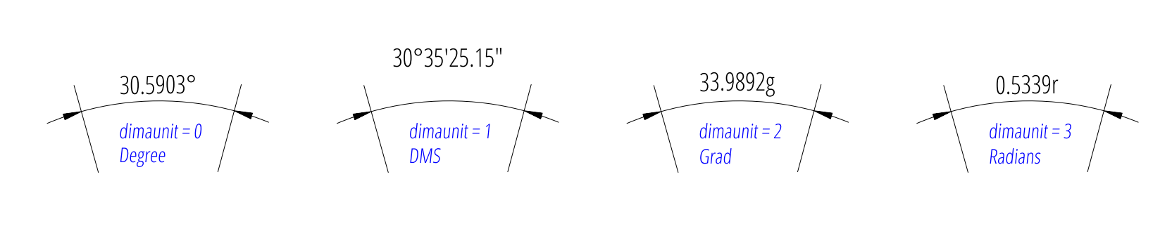
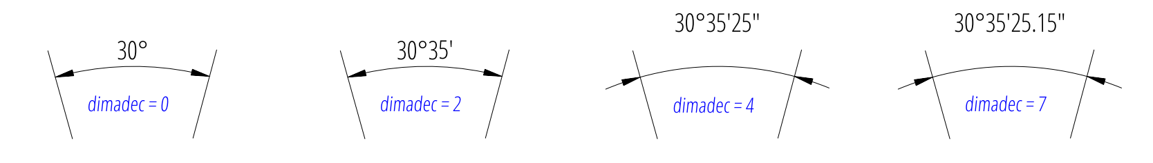
Angular Units
Angular units are set by dimaunit:
0 |
Decimal degrees |
1 |
Degrees/Minutes/Seconds,
|
2 |
Grad |
3 |
Radians |
d1 = 15
d2 = 15.59031944
for x, (dimaunit, dimadec) in enumerate(
    [
        (0, 4),
        (1, 7),
        (2, 4),
        (3, 4),
    ]
):
    dim = msp.add_angular_dim_cra(
        center=(x * 4.0, 0.0),
        radius=3.0,
        distance=1.0,
        start_angle=90.0 - d1,
        end_angle=90.0 + d2,
        override={
            "dimaunit": dimaunit,
            "dimadec": dimadec,
        },
    )
    dim.render()
Overriding Measurement Text
See Linear Dimension Tutorial: Overriding Measurement Text
Measurement Text Formatting and Styling
See Linear Dimension Tutorial: Measurement Text Formatting and Styling
Tolerances and Limits
See Linear Dimension Tutorial: Tolerances and Limits