Tutorial for Finding Chains and Loops
Added in version 1.4.
This tutorial shows how to find connected structures like open or closed polylines
by the ezdxf.edgeminer and the ezdxf.edgesmith modules.
Introduction
The main goal of the ezdxf.edgeminer module is to find connected edges in a heap
of unordered edges.
The module is designed to work with anything that has a start- and end point and knows nothing about the edge itself except for the optional length. Therefore intersection points between edges are not known.
1. Step: Create Edges
The companion module ezdxf.edgesmith creates the required edges from DXF
primitives like LINE, ARC, ELLIPSE, SPLINE and POLYLINE.
The current implementation of the edgesmith module is restricted to work
with 2D structures. Every edge is projected onto the xy-plane of the WCS.
2. Step: Find Chains and Loops
The edgeminer module provides functions to search for open chains and
closed loops:
3. Step: Build Polylines and Paths
From the chains and loops found, you can build new polylines and boundary paths for hatches:
Terminology
This is a short summary, for more information see: ezdxf.edgeminer
- Edge
A linear connection between two points.
- Leaf
A leaf is a loose end of an edge, which is not connected to other edges.
- Junction
A junction has more than two adjacent edges.
- Chain
A chain has sequential connected edges. The end point of an edge is connected to the start point of the following edge.
- Simple Chain
A simple chain starts and ends with a leaf or a junction.
- Open Chain
An open chain starts and ends with a leaf.
- Loop
A loop is a simple chain with connected start- and end vertices.
Join Ordered Entities to Polylines
The first example uses an exploded polyline to show how to search for connected edges, when the edges are ordered.
import random
import ezdxf
from ezdxf import edgeminer, edgesmith

doc = ezdxf.new()
doc.header["$LWDISPLAY"] = 1
msp = doc.modelspace()

lwp = msp.add_lwpolyline(
    [(0, 0), (5, 0, -0.5), (5, 5), (0, 5)],
    format="xyb",
    close=True,
    dxfattribs={"layer": "SOURCE", "color": 2, "lineweight": 30},
)
# create lines and arcs from LWPOLYLINE
entities = lwp.explode()
The orientation of the entities looks like this:
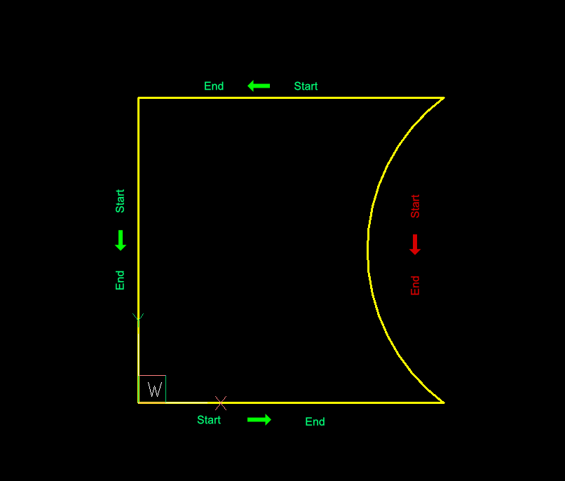
ARC entities are always counter-clockwise oriented, so the start- and end points of the adjacent lines are not connected in start/end order.
The ezdxf.edgeminer.find_sequential_chain() function is the right tool for this
task. It searches sequential ordered edges and reverses those, where the start- and end
point doesn’t match. The search stops at the first edge that doesn’t have a matching
start- or end point or a closed loop was found.
create edges from DXF entities
find connected edges
create LWPOLYLINE from connected edges
# 1. create edges from DXF entities
edges = list(edgesmith.edges_from_entities_2d(entities))
# 2. search for connected edges
chain = edgeminer.find_sequential_chain(edges)
# 3. create a LWPOLYLINE from connected edges
lwp2 = edgesmith.lwpolyline_from_chain(
    chain, dxfattribs={"layer": "LWPOLYLINE", "color": 1, "lineweight": 30}
)
msp.add_entity(lwp2)
doc.saveas("result1.dxf")
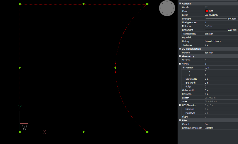
The new created LWPOLYLINE in BricsCAD:
Join Unordered Entities to Polylines
For the search in a heap of unordered edges is an additional object required.
A ezdxf.edgeminer.Deposit has a spatial search tree to optimize the
search for unordered edges.
The ezdxf.edgeminer.find_simple_chain() function starts at an edge and searches in
both directions via the spatial search tree for connected edges. The search stops at a
leaf, a junction or when a closed loop was found.
# create a new doc
doc = ezdxf.new()
doc.header["$LWDISPLAY"] = 1
msp = doc.modelspace()

# reuse same entities from previous example
edges = list(edgesmith.edges_from_entities_2d(entities))

# shuffle the ordered edges
random.shuffle(edges)

# a deposit optimizes the search for unordered edges
deposit = edgeminer.Deposit(edges)

# start the search at an arbitrary edge
start = edges[0]
chain = edgeminer.find_simple_chain(deposit, start)
lwp3 = edgesmith.lwpolyline_from_chain(
    chain, dxfattribs={"color": 1, "lineweight": 30}
)
msp.add_entity(lwp3)
doc.saveas("result2.dxf")
The result is the same as in “result1.dxf”.
The following functions are for situations when you don’t know where to start.
ezdxf.edgeminer.find_all_simple_chains(): returns all chains that start and end with a leaf or a junction
ezdxf.edgeminer.find_all_open_chains(): returns all chains from the deposit that start and end with a leaf. Warning: recursive backtracking!
ezdxf.edgeminer.find_loop(): returns the first loop found in the deposit. Warning: recursive backtracking!
ezdxf.edgeminer.find_all_loops(): returns all possible loops found in the deposit. Warning: recursive backtracking!
Join Entities to Hatches
Creating hatches from edges is similar to creating polylines.
# create a new doc
doc = ezdxf.new()
doc.header["$LWDISPLAY"] = 1
msp = doc.modelspace()

# 1. create a HATCH
hatch = msp.add_hatch(color=2)

# reuse same entities from previous example
edges = list(edgesmith.edges_from_entities_2d(entities))

# shuffle the ordered edges
random.shuffle(edges)

# a deposit optimizes the search for unordered edges
deposit = edgeminer.Deposit(edges)

# start the search at an arbitrary edge
start = edges[0]

# 2. find edges
chain = edgeminer.find_simple_chain(deposit, start)

# 3. create a polyline boundary path from edges
boundary_path = edgesmith.polyline_path_from_chain(chain)

# 4.add boundary path to HATCH
hatch.paths.append(boundary_path)
doc.saveas("hatch1.dxf")
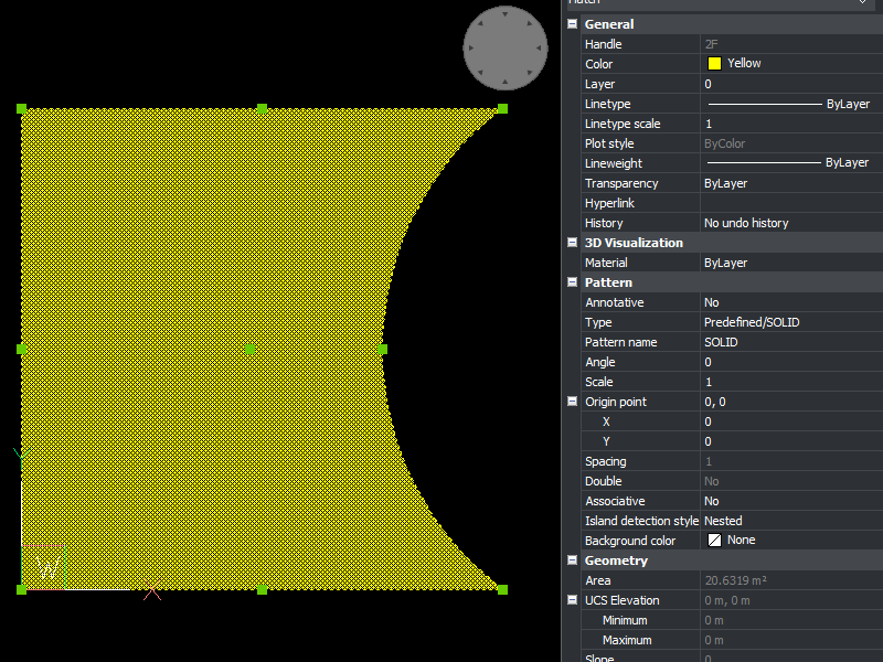
The new created HATCH in BricsCAD:
How Are 3D Entities Handled?
The ezdxf.edgeminer module is designed to be as versatile as possible and uses
3D coordinates for all vertices. So edges are only connected when the x-, y- and
z-coordinates of their vertices are close together.
The ezdxf.edgesmith module is designed to avoid the complexity of 3D entities and
handles only 2D entities by setting all z-coordinates to 0.
Therefore all vertices are projected onto the xy-plane of the
WCS and if an entity can not represent such a projection the entity will be flattened
into line segments.
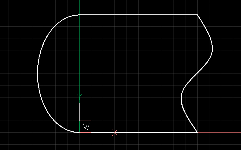
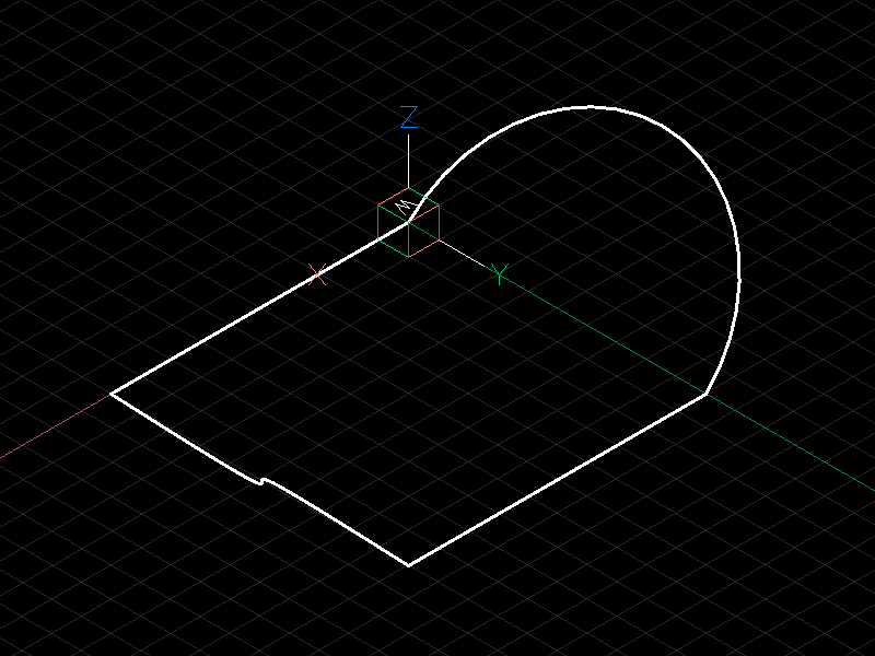
This example includes an ARC and a SPLINE in 3D space:
doc = ezdxf.readfile("edges_3d.dxf")
msp = doc.modelspace()

# create edges and search index
edges = list(edgesmith.edges_from_entities_2d(msp))
deposit = edgeminer.Deposit(edges)
# find a chain
chain = edgeminer.find_simple_chain(deposit, edges[0])
# add a hatch and add the boundary path
hatch = msp.add_hatch(color=5)
boundary_path = edgesmith.polyline_path_from_chain(chain, max_sagitta=0.01)
hatch.paths.append(boundary_path)
doc.saveas("flattened_hatch.dxf")
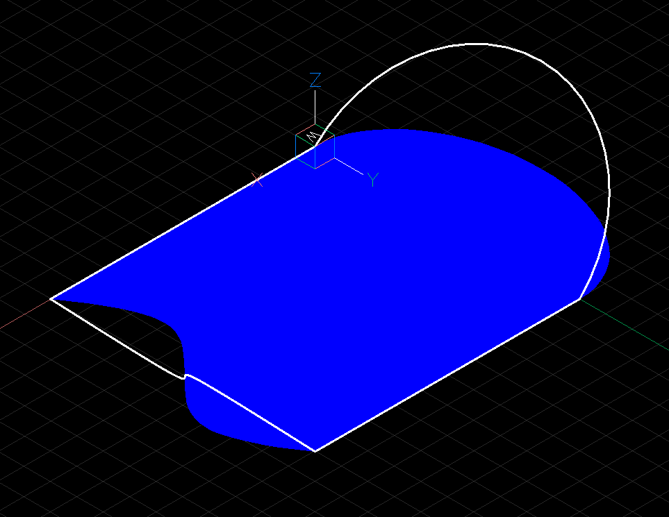
The hatch is projected onto the xy-plane of the WCS:
To process only 2D entities us the filter_2d_entities()
function that returns only pure 2D entities and ignores all entities placed outside or
extending beyond the xy-plane.
Junctions
A junction is a vertex with a degree of 3 or more and adds complexity to the task of
finding geometry. There is not a single solution that fits all needs and some goals are
not achievable by the ezdxf.edgeminer module.
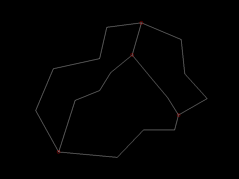
This is the starting point for the following examples, each red circle marks a junction:
You can check the complexity of your problem by printing the degree-counter:
print(deposit.degree_counter())
Output:
Counter({2: 15, 3: 4})
There a 15 vertices of degree 2 (good) and 4 vertices of degree 3 (bad).
Find All Simple Chains
A simple chain starts and ends with a leaf or a junction, hence there are no decisions to make and and finding them is also fast by using a spatial search index.
# load data
doc = ezdxf.readfile("junctions.dxf")
msp = doc.modelspace()
lines = msp.query("LINE")

# create edges and search index
edges = list(edgesmith.edges_from_entities_2d(lines))
deposit = edgeminer.Deposit(edges)

# find chains
chains = edgeminer.find_all_simple_chains(deposit)

# create a new output document
out = ezdxf.new()
msp = out.modelspace()
color = 1
for chain in chains:
    polyline = edgesmith.lwpolyline_from_chain(
        chain, dxfattribs={"color": color}
    )
    msp.add_entity(polyline)
    color += 1
out.saveas("simple_chains.dxf")
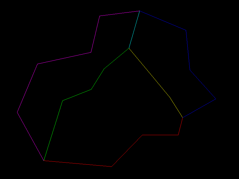
Each color represents a separated LWPOLYLINE:
Find All Loops
This task is harder and an edge can be part of multiple solutions:
# same code as in the previous example til here
# find chains
loops = edgeminer.find_all_loops(deposit)

# create a new output document
out = ezdxf.new()
msp = out.modelspace()
color = 1
for loop in loops:
    layer = f"LOOP_{color}"
    polyline = edgesmith.lwpolyline_from_chain(
        loop, dxfattribs={"color": color, "layer": layer}
    )
    msp.add_entity(polyline)
    color += 1
out.saveas("loops.dxf")
These are 6 of the 7 solutions, the 7th solution is the dashed line:
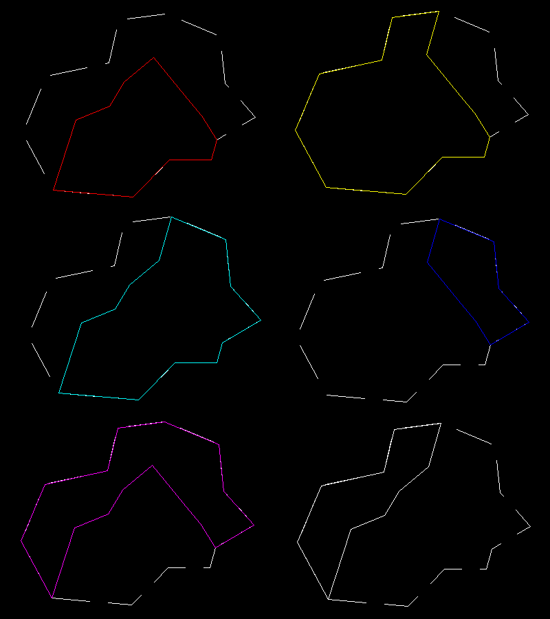
The find_all_loops() function is a recursive backtracking
algorithm and has a complexity of O(n!), therefore all recursive search functions
have a timeout argument to finish the task before the universe ends.
These helper functions may help you to choose a solution, but the default length calculation for edges is not precise!
Find One Loop For a Given Edge
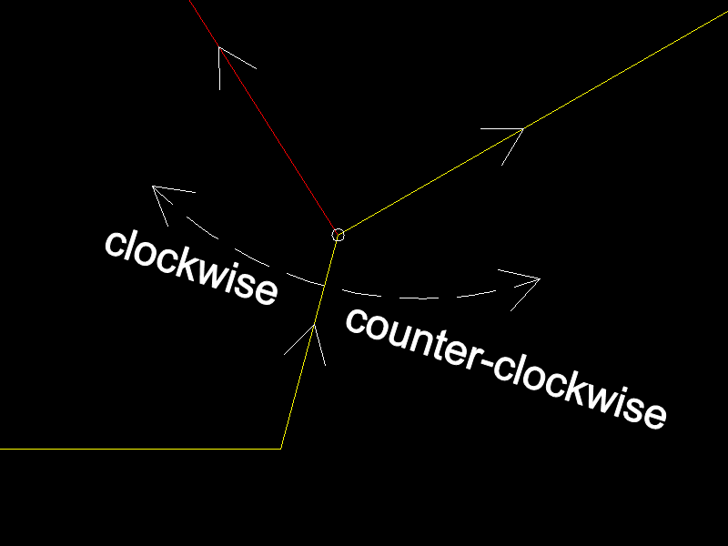
The find_loop_by_edge() function starts at a given edge and has a
preferred clockwise or counter-clockwise search order. The algorithm chooses the
next edge at a junction in clockwise order if the argument clockwise is True
otherwise the first counter-clockwise edge. This is a fast non-recursive algorithm.
edges = list(edgesmith.edges_from_entities_2d(lines))
deposit = edgeminer.Deposit(edges)

# choose an edge to start with
start = edges[0]
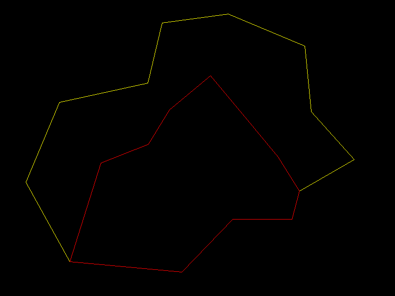
loop1 = edgeminer.find_loop_by_edge(deposit, start, clockwise=True)
loop2 = edgeminer.find_loop_by_edge(deposit, start, clockwise=False)
Red is the clockwise solution and yellow is the counter-clockwise solution:
Find Loop by Pick-Point
The CAD functionality to select a HATCH boundary path by picking a point inside the boundary is a bit tricky, but can be achieved by combining some tools.
find a starting edge near the pick-point
find candidates by the
find_loop_by_edge()function for both search orderssort candidates by area
take the smallest loop which contains the pick-point
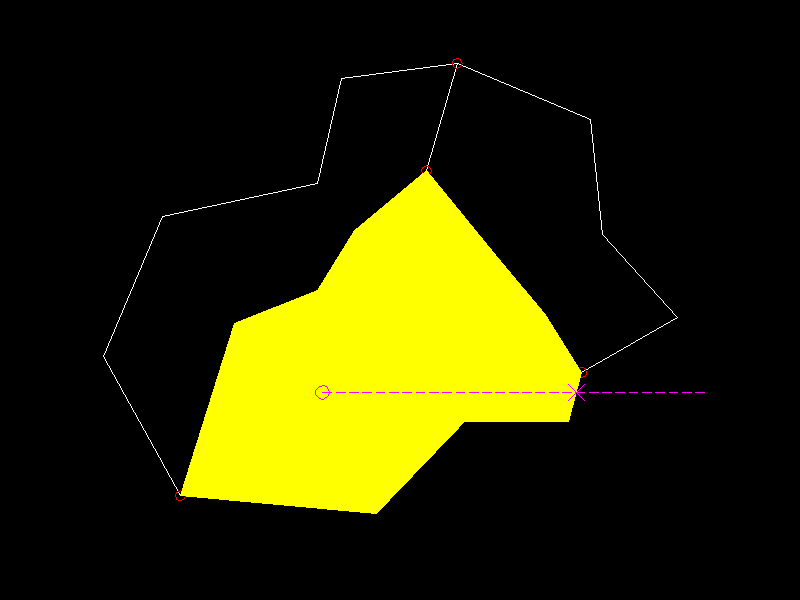
The function intersecting_edges_2d() tests all edges for an
intersection with a line starting at the pick-point and ending outside the bounding box
of all vertices. Any loop containing the pick-point has at least one edge that
intersects this line.
doc = ezdxf.readfile("junctions.dxf")
msp = doc.modelspace()
lines = msp.query("LINE")
edges = list(edgesmith.edges_from_entities_2d(lines))
pick_point = (110, 50)

# 1. find a starting edge near the pick-point
intersecting_edges = edgesmith.intersecting_edges_2d(edges, pick_point)
if not len(intersecting_edges):
    print("no intersection found")
    return
hatch = msp.add_hatch(color=2)

# The intersecting edges are sorted by ascending distance to the pick-point
# take the closest edge as starting edge:
start = intersecting_edges[0].edge

# 2. find the best loop candidates
deposit = edgeminer.Deposit(edges)
candidates = [
    edgeminer.find_loop_by_edge(deposit, start, clockwise=True),
    edgeminer.find_loop_by_edge(deposit, start, clockwise=False),
]

# 3. sort candidates by area
candidates.sort(key=edgesmith.loop_area)
for loop in candidates:
    # 4. take the smallest loop which contains the pick-point
    if edgesmith.is_inside_polygon_2d(loop, pick_point):
        hatch.paths.append(edgesmith.polyline_path_from_chain(loop))
        break
else:  # for loop ended without break
    print("no loop found")
    return
doc.saveas("find_loop_by_pick_point.dxf")
I am not convinced that this is the best solution or that this solution works for all
use cases, therefore this is not (yet) a helper function in the edgesmith module.
Gaps and Design Inaccuracies
Most real-world DXF drawings have design inaccuracies, that means, there are gaps between the endpoints of entities.
All search and test functions have an optional argument gap_tol or the gap
tolerance is stored in the Deposit class.
The gap tolerance is the maximum distance between two edge vertices to consider them
as connected. It is important to use the same tolerance throughout a task, from creating
the edges til building new DXF entities from chains and loops.
Specialty Edge Paths
AutoCAD is very picky about edge paths in HATCH entities when it comes to considering
them as closed. Therefore the edge_path_from_chain() function adds additional line
segments between edges when the gap is larger than LEN_TOL, LEN_TOL is a constant
value of 1e-9.
Coincident Edges
Coincident edges in the context of edgeminer are edges where the start- and the end vertex
are coincident, remember: the shape of the edge is not known. This is the reason why such
edges are not removed automatically, e.g. two arcs can create a closed loop as coincident
edges:
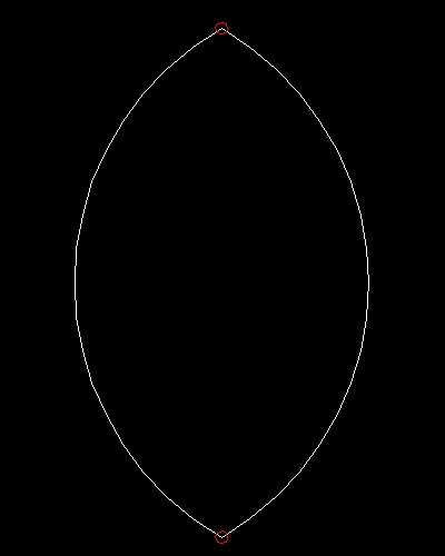
Coincident edges are a major nuisance and should be avoided at all costs. They create ambiguity and can be the reason why the expected results are not found.
The filter_coincident_edges() function removes coincident edges.
It takes a function to test if two edges are coincident and the default function tests
only if the end points are coincident, but you can pass a more sophisticated function.
Set Operations
The ezdxf.edgeminer.Edge class implements the __hash__() method and can be
used in sets, this allows set operations like subtracting a found loop from the source
edges:
edges = list(edgesmith.edges_from_entities_2d(lines))
deposit = edgeminer.Deposit(edges)

# returns the first loop found
first_loop = edgeminer.find_loop(deposit)
edges = list(set(edges) - set(first_loop))

# or use this helper function:
edges = edgeminer.subtract_edges(edges, first_loop)
The Deposit has to be recreated for the new list of edges!