Tutorial for Viewports in Paperspace
This tutorial is based on the example script viewports_in_paperspace.py. The script creates DXF files for the version R12 and for R2000+, but the export for DXF R12 has a wrong papersize in BricsCAD and wrong margins in Autodesk DWG Trueview. I don’t know why this happens and I don’t waste my time to fix this.
Important
If you need paperspace layouts use DXF version R2000 or newer because the export of the page dimensions does not work for DXF R12!
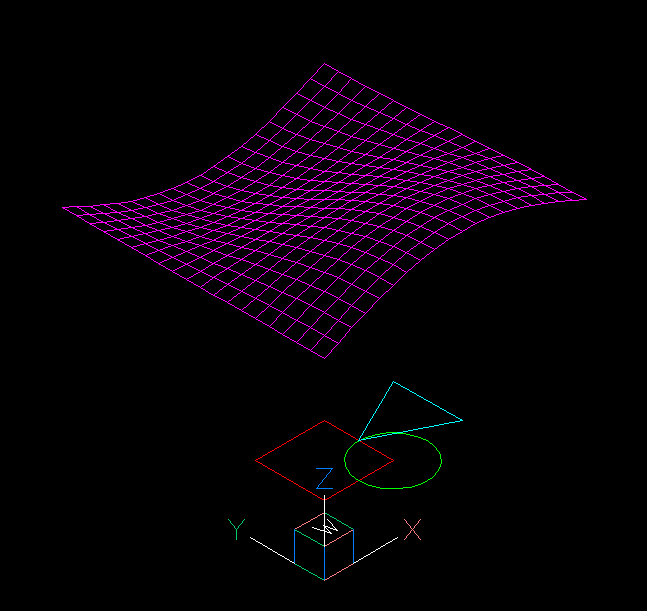
The scripts creates three flat geometries in the xy-plane of the WCS and a 3D mesh as content of the modelspace:
Page Setup
The paperspace layout feature lacks documentation in the DXF reference, there is no information in practice on how it is used, so most of the information here is assumptions gathered through trail and error.
The page_setup() method defines the properties
of the paper sheet itself. The units of the modelspace and the paperspace are
not related and can even have different unit systems (imperial, meters), but to
keep things simple it’s recommended to use the same unit system for both spaces.
layout.page_setup(size=(24, 18), margins=(1, 1, 1, 1), units="inch")
The size argument defines the overall paper size in rotation mode 0, it seems to be the best practice to define the paper extents in landscape mode and rotate the paper by the rotate argument afterwards.
Choices for the rotation argument:
0
no rotation
1
90 degrees counter-clockwise
2
upside-down
3
90 degrees clockwise
The scale argument reflects the relationship between paper unit and drawing unit in paperspace. It’s recommended to let this scale at the default value of 1:1 and draw lines and text in paperspace with the same units as you defined the paper size.
See also
AutoCAD: About Plotting and About Setting the Plot Scale
BricsCAD: General Procedure for Printing
Drawing in Paperspace
You can add DXF entities to the paperspace like to any other layout space. The coordinate origin (0, 0) is in the left bottom corner of the canvas which is the paper size minus the margins. You can draw beyond this limits but CAD applications may not print that content.
Hint
By writing this tutorial I noticed that changing the printer/plotter and the paper size does shift the layout content, because all paper sizes are defined without margins. Maybe it’s preferable to set all margins to zero.
I added the helper method page_setup() to the
Drawing class and an example simple_page_setup.py
how to use it.
Adding Viewports
The Viewport entity is a window to the modelspace to
display the content of the modelspace in paperspace with an arbitrary scaling
and rotation.
The VIEWPORT entity will be added by the factory method add_viewport(),
the center argument defines the center and the size argument defines the
width and height of the of the VIEWPORT in paperspace. The source of the
modelspace to display is defined by the arguments view_center_point and
view_height.
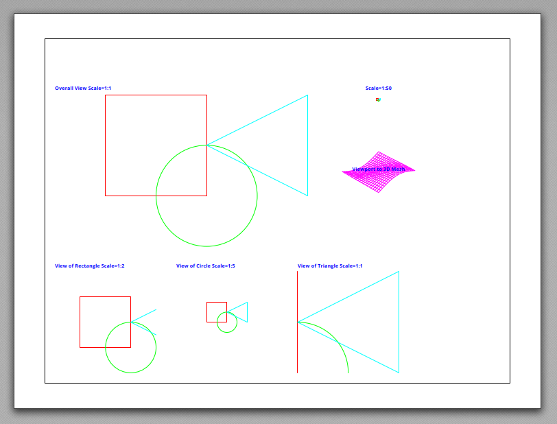
Scaling Factor
The scaling factor of the VIEWPORT is not an explicit value, the factor is defined by the relation of the VIEWPORT height of the size argument and the view_height argument.
If both values are equal the scaling is 1:1
paperspace.add_viewport(
    center=(14.5, 2.5),
    size=(5, 5),
    view_center_point=(12.5, 7.5),
    view_height=5,
)
If the view_height is 5x larger than the VIEWPORT height the scaling is 1:5
paperspace.add_viewport(
    center=(8.5, 2.5),
    size=(5, 5),
    view_center_point=(10, 5),
    view_height=25,
)
View Direction
The default view direction is the top down view, but can be changed to any view
by the attributes view_target_point and view_direction_vector of the
dxf namespace.
vp = paperspace.add_viewport(
    center=(16, 10), size=(4, 4), view_center_point=(0, 0), view_height=30
)
vp.dxf.view_target_point = (40, 40, 0)
vp.dxf.view_direction_vector = (-1, -1, 1)
Viewport Frame
The VIEWPORT frame (borderlines) are shown in paperspace by default. The VIEWPORT entity does not have an attribute to change this. The visibility of the VIEWPORT frame is controlled by the layer assigned to the VIEWPORT entity which is the layer “VIEWPORTS” by default in ezdxf. Turning off this layer hides the frames of the VIEWPORT entities on this layer, to do that the layer “VIEWPORTS” have to be created by the library user:
vp_layer = doc.layers.add("VIEWPORTS")
vp_layer.off()
Freeze Layers
Each VIEWPORT can have individual frozen layers, which means the layers are not
visible in this VIEWPORT. To freeze layers in a VIEWPORT assign the names of the
frozen layers as a list-like object to the frozen_layers attribute of the
VIEWPORT entity:
vp.frozen_layers = ["Layer0", "Layer1"]
Important
AutoCAD and BricsCAD do not crash if the layer names do not have layer table entries and the layer names are case insensitive as all table names.
Override Layer Properties
Each VIEWPORT can override layer properties individually. These overrides are
stored in the Layer entity and referenced by the handle
of the VIEWPORT. This procedure is a bit more complex and shown in the example
file viewports_override_layer_attributes.py.
get the
Layerobjectget the
LayerOverridesobject from the layeroverride the properties of the VIEWPORT
commit changes
layer = doc.layers.get("Layer0")
override = layer.get_vp_overrides()
override.set_linetype(vp.dxf.handle, "DASHED")
override.commit()
Supported property overrides:
ACI color
true color
transparency
linetype
lineweight
See also
Basic concept of Layers
Basic concept of AutoCAD Color Index (ACI)
Basic concept of True Color
Basic concept of Transparency
Basic concept of Linetypes
Basic concept of Lineweights