VPORT Configuration Table
The VPORT table stores the modelspace viewport configurations. A viewport configuration is a tiled view of multiple viewports or just one viewport.
In contrast to other tables the VPORT table can have multiple entries with the same name,
because all VPORT entries of a multi-viewport configuration are having the same name -
the viewport configuration name. The name of the actual displayed viewport configuration
is '*ACTIVE', as always table entry names are case insensitive
('*ACTIVE' == '*Active').
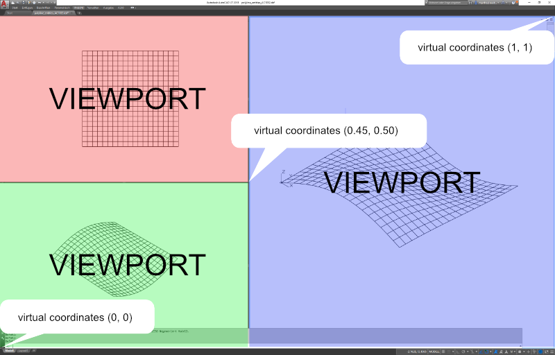
The available display area in AutoCAD has normalized coordinates, the lower-left corner
is (0, 0) and the upper-right corner is (1, 1) regardless of the true aspect ratio and
available display area in pixels. A single viewport configuration has one VPORT entry
'*ACTIVE' with the lower-left corner (0, 0) and the upper-right corner (1, 1).
The following statements refer to a 2D plan view: the view-target-point defines the origin of the DCS (Display Coordinate system), the view-direction vector defines the z-axis of the DCS, the view-center-point (in DCS) defines the point in modelspace translated to the center point of the viewport, the view height and the aspect-ratio defines how much of the modelspace is displayed. AutoCAD tries to fit the modelspace area into the available viewport space e.g. view height is 15 units and aspect-ratio is 2.0 the modelspace to display is 30 units wide and 15 units high, if the viewport has an aspect ratio of 1.0, AutoCAD displays 30x30 units of the modelspace in the viewport. If the modelspace aspect-ratio is 1.0 the modelspace to display is 15x15 units and fits properly into the viewport area.
But tests show that the translation of the view-center-point to the middle of the viewport not always work as I expected. (still digging…)
Note
All floating point values are rounded to 2 decimal places for better readability.
DXF R12
Multi-viewport configuration with three viewports.
0       <<< table start
TABLE
2       <<< table type
VPORT
70      <<< VPORT table (max.) count, not reliable (ignore)
3
0       <<< first VPORT entry
VPORT
2       <<< VPORT (configuration) name
*ACTIVE
70      <<< standard flags, bit-coded
0
10      <<< lower-left corner of viewport
0.45    <<<     x value, virtual coordinates in range [0 - 1]
20      <<<     group code for y value
0.0     <<<     y value, virtual coordinates in range [0 - 1]
11      <<< upper-right corner of viewport
1.0     <<<     x value, virtual coordinates in range [0 - 1]
21      <<<     group code for y value
1.0     <<<     y value, virtual coordinates in range [0 - 1]
12      <<< view center point (in DCS), ???
13.71   <<<     x value
22      <<<     group code for y value
0.02    <<<     y value
13      <<< snap base point (in DCS)
0.0     <<<     x value
23      <<<     group code for y value
0.0     <<<     y value
14      <<< snap spacing X and Y
1.0     <<<     x value
24      <<<     group code for y value
1.0     <<<     y value
15      <<< grid spacing X and Y
0.0     <<<     x value
25      <<<     group code for y value
0.0     <<<     y value
16      <<< view direction from target point (in WCS), defines the z-axis of the DCS
1.0     <<<     x value
26      <<<     group code for y value
-1.0    <<<     y value
36      <<<     group code for z value
1.0     <<<     z value
17      <<< view target point (in WCS), defines the origin of the DCS
0.0     <<<     x value
27      <<<     group code for y value
0.0     <<<     y value
37      <<<     group code for z value
0.0     <<<     z value
40      <<< view height
35.22
41      <<< viewport aspect ratio
0.99
42      <<< lens (focal) length
50.0    <<< 50mm
43      <<< front clipping planes, offsets from target point
0.0
44      <<< back clipping planes, offsets from target point
0.0
50      <<< snap rotation angle
0.0
51      <<< view twist angle
0.0
71      <<< view mode
0
72      <<< circle zoom percent
1000
73      <<< fast zoom setting
1
74      <<< UCSICON setting
3
75      <<< snap on/off
0
76      <<< grid on/off
0
77      <<< snap style
0
78      <<< snap isopair
0
0       <<< next VPORT entry
VPORT
2       <<< VPORT (configuration) name
*ACTIVE <<< same as first VPORT entry
70
0
10
0.0
20
0.5
11
0.45
21
1.0
12
8.21
22
9.41
...
...
0       <<< next VPORT entry
VPORT
2       <<< VPORT (configuration) name
*ACTIVE <<< same as first VPORT entry
70
0
10
0.0
20
0.0
11
0.45
21
0.5
12
2.01
22
-9.33
...
...
0
ENDTAB
DXF R2000+
Mostly the same structure as DXF R12, but with handle, owner tag and subclass markers.
0       <<< table start
TABLE
2       <<< table type
VPORT
5       <<< table handle
151F
330     <<< owner, table has no owner - always #0
0
100     <<< subclass marker
AcDbSymbolTable
70      <<< VPORT table (max.) count, not reliable (ignore)
3
0       <<< first VPORT entry
VPORT
5       <<< entry handle
158B
330     <<< owner, VPORT table is owner of VPORT entry
151F
100     <<< subclass marker
AcDbSymbolTableRecord
100     <<< subclass marker
AcDbViewportTableRecord
2       <<< VPORT (configuration) name
*ACTIVE
70      <<< standard flags, bit-coded
0
10      <<< lower-left corner of viewport
0.45    <<<     x value, virtual coordinates in range [0 - 1]
20      <<<     group code for y value
0.0     <<<     y value, virtual coordinates in range [0 - 1]
11      <<< upper-right corner of viewport
1.0     <<<     x value, virtual coordinates in range [0 - 1]
21      <<<     group code for y value
1.0     <<<     y value, virtual coordinates in range [0 - 1]
12      <<< view center point (in DCS)
13.71   <<<     x value
22      <<<     group code for y value
0.38    <<<     y value
13      <<< snap base point (in DCS)
0.0     <<<     x value
23      <<<     group code for y value
0.0     <<<     y value
14      <<< snap spacing X and Y
1.0     <<<     x value
24      <<<     group code for y value
1.0     <<<     y value
15      <<< grid spacing X and Y
0.0     <<<     x value
25      <<<     group code for y value
0.0     <<<     y value
16      <<< view direction from target point (in WCS)
1.0     <<<     x value
26      <<<     group code for y value
-1.0    <<<     y value
36      <<<     group code for z value
1.0     <<<     z value
17      <<< view target point (in WCS)
0.0     <<<     x value
27      <<<     group code for y value
0.0     <<<     y value
37      <<<     group code for z value
0.0     <<<     z value
40      <<< view height
35.22
41      <<< viewport aspect ratio
0.99
42      <<< lens (focal) length
50.0    <<< 50mm
43      <<< front clipping planes, offsets from target point
0.0
44      <<< back clipping planes, offsets from target point
0.0
50      <<< snap rotation angle
0.0
51      <<< view twist angle
0.0
71      <<< view mode
0
72      <<< circle zoom percent
1000
73      <<< fast zoom setting
1
74      <<< UCSICON setting
3
75      <<< snap on/off
0
76      <<< grid on/off
0
77      <<< snap style
0
78      <<< snap isopair
0
281     <<< render mode 1-6 (... too many options)
0       <<< 0 = 2D optimized (classic 2D)
65      <<< Value of UCSVP for this viewport. (0 = UCS will not change when this viewport is activated)
1       <<< 1 = then viewport stores its own UCS which will become the current UCS whenever the viewport is activated.
110     <<< UCS origin (3D point)
0.0     <<<     x value
120     <<<     group code for y value
0.0     <<<     y value
130     <<<     group code for z value
0.0     <<<     z value
111     <<< UCS X-axis (3D vector)
1.0     <<<     x value
121     <<<     group code for y value
0.0     <<<     y value
131     <<<     group code for z value
0.0     <<<     z value
112     <<< UCS Y-axis (3D vector)
0.0     <<<     x value
122     <<<     group code for y value
1.0     <<<     y value
132     <<<     group code for z value
0.0     <<<     z value
79      <<< Orthographic type of UCS 0-6 (... too many options)
0       <<< 0 = UCS is not orthographic
146     <<< elevation
0.0
1001    <<< extended data - undocumented
ACAD_NAV_VCDISPLAY
1070
3
0       <<< next VPORT entry
VPORT
5
158C
330
151F
100
AcDbSymbolTableRecord
100
AcDbViewportTableRecord
2       <<< VPORT (configuration) name
*ACTIVE <<< same as first VPORT entry
70
0
10
0.0
20
0.5
11
0.45
21
1.0
12
8.21
22
9.72
...
...
0       <<< next VPORT entry
VPORT
5
158D
330
151F
100
AcDbSymbolTableRecord
100
AcDbViewportTableRecord
2       <<< VPORT (configuration) name
*ACTIVE <<< same as first VPORT entry
70
0
10
0.0
20
0.0
11
0.45
21
0.5
12
2.01
22
-8.97
...
...
0
ENDTAB