MESH Internals
The MESH entity is the compact version of the PolyFaceMesh implemented by the
Polyline entity . The entity stores the vertices, edges
and faces in a single entity and was introduced in DXF version R13/R14.
For more information about the top level stuff go to the
Mesh class.
See also
DXF Reference: MESH
ezdxf.entities.Meshclass
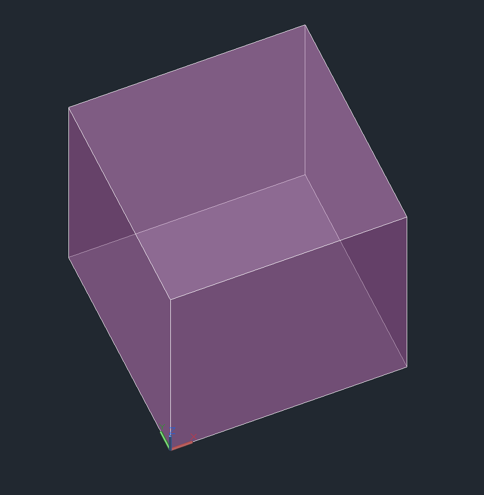
The following DXF code represents this cube with subdivision level of 0:
0
MESH            <<< DXF type
5               <<< entity handle
2F
330             <<< block record handle of owner layout
17
100
AcDbEntity
8
0               <<< layer
62
6               <<< color
100
AcDbSubDMesh    <<< subclass marker
71
2               <<< version
72
1               <<< blend crease, 1 is "on", 0 is "off"
91
0               <<< subdivision level is 0
92
8               <<< vertex count, 8 cube corners
10              <<< 1. vertex, x-axis
0.0
20              <<< y-axis
0.0
30              <<< z-axis
0.0
10              <<< 2. vertex
1.0
20
0.0
30
0.0
10              <<< 3. vertex
1.0
20
1.0
30
0.0
10              <<< 4. vertex
0.0
20
1.0
30
0.0
10              <<< 5. vertex
0.0
20
0.0
30
1.0
10              <<< 6. vertex
1.0
20
0.0
30
1.0
10              <<< 7. vertex
1.0
20
1.0
30
1.0
10              <<< 8. vertex
0.0
20
1.0
30
1.0
93              <<< size of face list
30              <<< size  = count of group code 90 tags = 6 x 5
90              <<< vertex count of face 1
4               <<< MESH supports ngons, count = 3, 4, 5, 6 ...
90
0       <<< face 1, index of 1. vertex
90
3       <<< face 1, index of 2. vertex
90
2       <<< face 1, index of 3. vertex
90
1       <<< face 1, index of 4. vertex
90
4               <<< vertex count of face 2
90
4       <<< face 2, index of 1. vertex
90
5       <<< face 2, index of 2. vertex
90
6       <<< face 2, index of 3. vertex
90
7       <<< face 2, index of 4. vertex
90
4               <<< vertex count of face 3
90
0       <<< face 3, index of 1. vertex
90
1       <<< face 3, index of 2. vertex
90
5       <<< face 3, index of 3. vertex
90
4       <<< face 3, index of 4. vertex
90
4               <<< vertex count of face 4
90
1       <<< face 4, index of 1. vertex
90
2       <<< face 4, index of 2. vertex
90
6       <<< face 4, index of 3. vertex
90
5       <<< face 4, index of 4. vertex
90
4               <<< vertex count of face 5
90
3       <<< face 5, index of 1. vertex
90
7       <<< face 5, index of 2. vertex
90
6       <<< face 5, index of 3. vertex
90
2       <<< face 5, index of 4. vertex
90
4               <<< vertex count of face 6
90
0       <<< face 6, index of 1. vertex
90
4       <<< face 6, index of 2. vertex
90
7       <<< face 6, index of 3. vertex
90
3       <<< face 6, index of 4. vertex
94              <<< edge count, each edge has exact two group code 90 tags
4               <<< the real edge count not the group code 90 tags!
90
0       <<< edge 1, vertex 1
90
1       <<< edge 1, vertex 1
90
1       <<< edge 2, vertex 1
90
2       <<< edge 2, vertex 2
90
2       <<< edge 3, vertex 1
90
3       <<< edge 3, vertex 2
90
3       <<< edge 4, vertex 1
90
0       <<< edge 4, vertex 2
95              <<< edge crease count, has to match edge count!
4
140
3.0     <<< crease value for edge 1
140
3.0     <<< crease value for edge 2
140
3.0     <<< crease value for edge 3
140
3.0     <<< crease value for edge 4
90              <<< property overwrite???
0
The edge and crease data have only a meaning if subdivision of the geometry will be applied! A crease value equal to the subdivision level prevents subdividing for the edge completely, a value between 0.0 and the subdivision level applies subdivision partially.
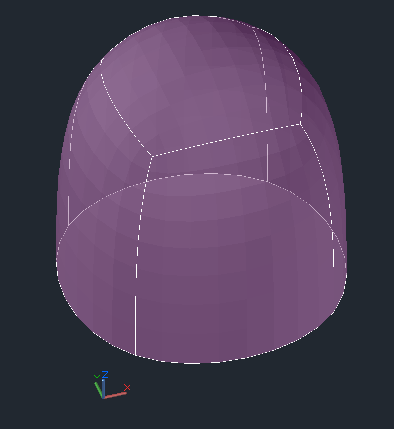
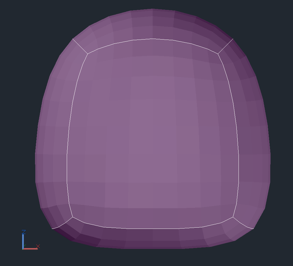
The cube with subdivision level of 3 and crease values of 3.0:
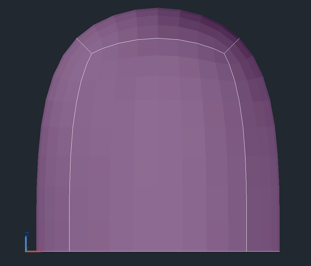
Front view for better details:
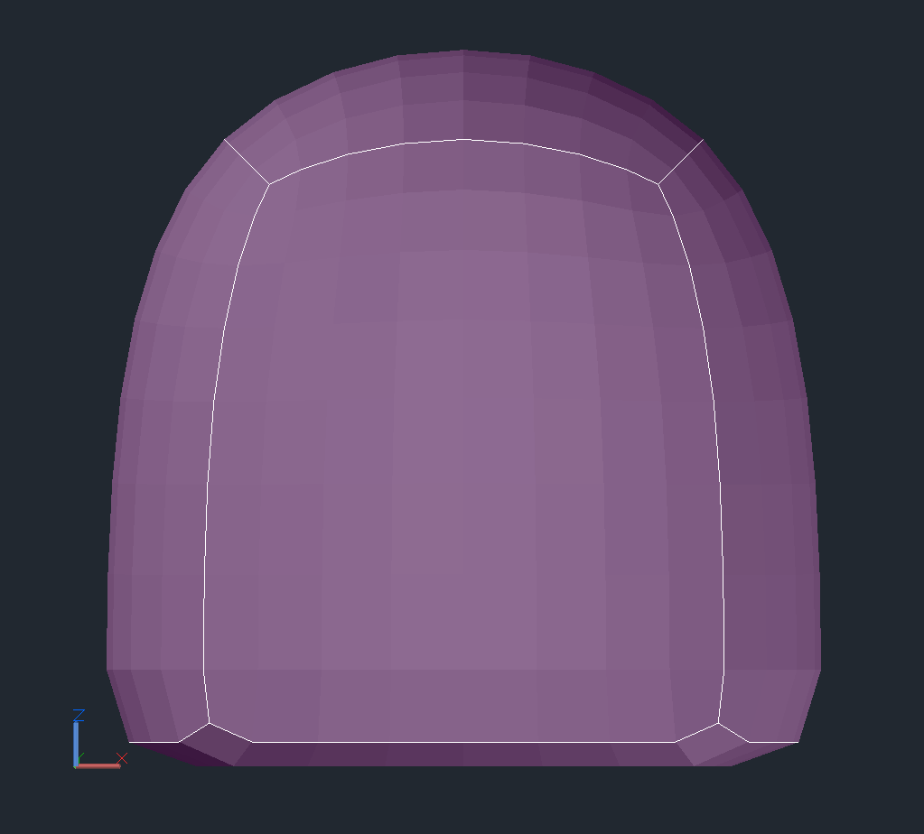
The cube with subdivision levels of 3 and crease values of 2.0:
The cube with subdivision level of 3 and crease values of 1.0:
The property overriding protocol is not documented in the DXF reference and currently I have no access to a CAD application which can created property overriding.